Product Description
|
Application |
|||||
|
• Agricultural equipment |
• Armament |
• Automobile industry |
• Computing equipment |
• Medical / dental instruments |
• Measuring instruments |
|
•Miscellaneous equipment |
•Pharmaceutical industry |
• Orthopedic implants |
• Safety equipment |
• Petrochemical industry |
• Industrial valves |
|
•Fixing and movable equipment |
• Sanitary fittings |
• General machinery |
• Pumps and general connections |
• Food and beverage processing |
• Instrumentation equipment |
| General Products Application/Service Area |
Metal Parts Solution for Vehicle, Agriculture machine, Construction Machine, |
| Main blank Process for Aluminum Casting | Die Casting, Permanent Molding /Gravity Casting, Low Pressure Casting, High Pressure Casting/Sand Casting, Extrusion Casting etc. |
| Blanks Tolerance -Casting Tolerance |
CT4-6 for Permanent Molding, Die Casting, CT 9-11 for Sand Casting |
| Applicable Material for casting |
A356.0/ZL101,GAlSi7Mg (3.2371.61)/AlSi7Mg/, A-S7G, Al Si Alloy, Al Cu Alloy ZL201 Al Mg Alloy ZL301,ZL302, |
| Casting Blank Size /Dimensions | 2 mm-1500mm / 0.08inch-60inch , or according to customer requirements |
| Casting Blank Weight | Range from 0.01kg-50kg |
| Applicable Machining Process |
CNC Machining/ Lathing/ Milling/ Turning/ Boring/ Drilling/ Tapping/ |
| Machining Tolerance | From 0.005mm-0.01mm-0.1mm |
| Machined Surface Quality | Ra 0.8-Ra3.2 according to customer requirement |
| Applicable Heat Treatment | T5~T6 |
| Applicable Finish Surface Treatment | Shot/sand blast, polishing, Primer Painting , Powder coating, ED- Coating, Finish Painting, Anodize (White or Black Color) |
| MOQ | For casting : 200pcs For Machining: 50pcs |
| Lead Time | 45days from the receipt date of deposit for aluminum die casting |
Products shown here are made to the requirements of specific customers and are illustrative of the types of manufacturing capabilities available within CHINAMFG group of companies. CHINAMFG policy is that none of these products will be sold to 3rd parties without written consent of the customers to whom the tooling, design and specifications belong.
Product Profile
| 1. Marterial percentage | alloy steel:45% carbon steel:35% stainless steel:10% iron:10% |
| 2. Casting weight percentage | 0.1-5kg:40% 5-20kg:30% 20-40kg:20% above 40kg:10% |
| 3. Industry percentage | Components for train & railway: 25% Components for automobile & truck: 30% Components for construction machinery & forklift: 25% Components for agricultural machinery: 10% Other machinery compponents: 10% |
| 4. Globa market share | United States:30% Europe:35% Japan& Korea:15% Domestic market:15% Other:5% |
| 5. Production capacity | Production Capacity: 20,000 tons / year The Current Production Output: 15,000 tons / year Open Capacity Percentage: 25% |
Manufacturing Process
Process design⇒ Tooling making ⇒ Wax injection ⇒Wax pattern assembly⇒ Mold preheat ⇒ Wax removal ⇒Stuccoing ⇒Dipping Casting⇒ Mold shake out ⇒Work piece cut-off ⇒ Grinding ⇒ Pack& transport ⇒ Final inspection ⇒Machining ⇒ Heat treatment
APQP and Inspection Report
| APQP-Casting 1. Process Flow Diagrams 2. Control Plan 3. Process FMEA 4. Casting Process Instruction 5. Solidification Simulation Report 6. Heat Treatment Work Instruction 7. Casting Final Quality Control WI 8. Visual Inspection VI For Surface Irregularities |
Inspection Report-Casting 1. Material Test Report(A) 2. Material Test Report(B) 3. Magnetic Particle Inspection Report 4. Ultrasonic Examination Report 5. Radiographic Test Report 6. Destructive Test Report 7. Coating Test Report 8. Visual Inspection Report 9. Casting Inspection Report |
| APQP-Machining 1. Process Flow Diagrams 2. Control Plan 3. Process FMEA 4. Machining Process Instruction 5. Gauge List And Validation Plan 6. Final Quality Control |
Other Quality Document 1. PPAP Checklist 2.Measurement System Analysis Study 3. Process Capability Studies 4. Corrective Action Report(8D) 5. Packaging Instruction |
|
Inspection Report-Machining 1. Dimensional Inspection Report(A) 2. Dimensional Inspection Report(B) 3. CMM Report |
|
Key Testing Equipment
|
Application |
|||||
|
• Agricultural equipment |
• Armament |
• Automobile industry |
• Computing equipment |
• Medical / dental instruments |
• Measuring instruments |
|
•Miscellaneous equipment |
•Pharmaceutical industry |
• Orthopedic implants |
• Safety equipment |
• Petrochemical industry |
• Industrial valves |
|
•Fixing and movable equipment |
• Sanitary fittings |
• General machinery |
• Pumps and general connections |
• Food and beverage processing |
• Instrumentation equipment |
Send Inquiry>>>
Our Company
ZheJiang CHINAMFG Machinery Manufacture Co., Ltd.
–Branch of CHINAMFG Industry Ltd.
We specialize in Metal Parts Solution for Vehicle, Agriculture machine, Construction Machine, transportation equipment, Valve and Pump system.
With keeping manufacturing process design, quality plHangZhou, key manufacturing processes and final quality control in house.
We are mastering key competence to supply quality mechanical parts and assembly to our customers for both Chinese and Export Market.
To satisfy different mechanical and functional requirements from our customers we are making a big range of metal products for our clients on base of different blanks solutions and technologies.
These blanks solutions and technologies include processes of Iron Casting, Steel Casting, Stainless Steel Casting, Aluminum Casting and Forging.
During the early involvement of the customer’s design process we are giving professional input to our customers in terms of process feasibility, cost reduction and function approach.
You are welcome to contact us for technical enquiry and business cooperation.
Our Team
Why Choose Us ?
YOUR DESIGN WE HELP TO ACHIEVE, AS YOUR SINCERE PARTNER
1. Over 15 years professional manufacture experience. → We know better to your needs.
2. One-stop Service of Custom mold design from Initial drawing design, Material selection assistance, Mold structure/Mold flow analysis, Trial & mass production to Final assembly & shipment. → To ensure you get finished products with good assembly function.
3. High skilled and well-trained working team under good management environment. → To make sure high quality of your products.
4. Large and strong production capacity. → To meet your high demands very well.
5.Best price based on same quality requirements. →To help your project with most economical solution.
6. We have very strict quality control process as below. → To deliver the qualified products for you.
In coming Quality control (IQC) : All incoming raw material are checked before used.
In process quality control (IPQC) : Perform inspections during the manufacturing process.
Final quality control (FQC) : All finished goods are inspected according to our quality standard for each products.
Outgoing Quality Control (OQC) : Our QC team will 100% full inspection before it goes out for shipment.
7.Reliable Package & flexible in-time delivery. →To guarantee the product are well received in your side.
8. 24 hours on-line service with quick response. → To support your any inquiry or question.
Customer photos
Core Competence
Advantages 1:High Engineering and Technical Capability
* An industry’s senior engineering technical team , with special skills and rich experience in product design, casting ,heat treating and machining fields.
* Based on customer needs, in the beginning of product development, offer a solution, casting design, by structural component designed to casting parts, optimize the product design, then reduce costs and creating the more value for the customers.
* Special Techniques Enable us to Be Competent with Those Difficulties at Wax Injection & Shell Making Procedures When Manufacturing the Parts with Inner-Sophisticated-Structures.
* Use casting simulation analysis system software, try our best to ensure the success of the one-time trial sample.
Advantages 2: Advanced Inspection Equipment & Strong Quality Assurance Capacity
* Our testing equipments are not only leading in the industry, and also has a very complete range, they are hardware guarantee to ensure us continue to provide high-quality products for our customers.
* Carrying out ISO9001 and TS16949 quality management system, full implementation of 5S and Kanban site management, which is software guarantee of the quality.
* IQC, IPQC and FQC quality management team to control the whole production process, effectively prevent the generation of unqualified product.
* Our casting’ PPM ≤1000 Machining ‘ PPM ≤600
* We sticks to the quality management philosophy that “Starting from the customer needs and ending with their satisfaction,focusing on customer demands and exceeding their expectations”
Advantages3: Good Customer Service
* CHINAMFG can provide customers with good service, our staff have abundant commercial experience, good language ability, and rich foundry or mechanical background. We are committed to providing customers with accurate, careful and speedy service.
* Quotation, Quality Complaints and Email Response can usually be quickly and efficiently feedback within 48 hours.
* We have carried out an information-based management which is driven by an ERP and PMC system, to ensure on time delivery rate:95%
Advantages 4: Powerful Deep-processing Ability It is our core competitive ability in the industry
* Machining capability as the same as casting, the machining facility is fully independent from the casting foundry and has an independent management team and tailored business model to suit.
* CHINAMFG has completed a transformation and upgraded to a deep-processing manufacturer with expanded production capabilities and is committed to be equipped with other capabilities except casting, we focus on developing terminal products for top-end markets.
* High technical content in machining, and casting with sheet metal, welding, assembling, CHINAMFG has the most competitive advantage, it is the good choice for you.
Packaging & Shipping
1, Bundles Packing: Inside: packed with plastic protective film to protect each piece. Outside: Wrap to be bundles by waterproof
craft paper or EPE film.
2, Carton Packing: Inside: Each pcs pack in 1 plastic bag. Outside: Numbers of quantity put in 1 carton.
3, Wood Pallet Packing: Inside: Bundles or cartons packing; Outside: Numbers of bundles or cartons laden on 1 wood pallet.
4, Customized Packing As Clients Request is Available.
FAQ:
1. Are you a manufacturer or a trading company?
We are a professional manufacturer with over 15 years’ export experience for designing and producing vehicle machinery parts.
2. How can I get some samples?
If you need, we are glad to offer you samples for free, but the new clients are expected to pay the courier cost,
and the charge will be deducted from the payment for formal order.
3. Can you make casting according to our drawing?
Yes, we can make casting according to your drawing, 2D drawing, or 3D cad model. If the 3D cad model can be supplied,
the development of the tooling can be more efficient. But without 3D, based on 2D drawing we can still make the samples properly approved.
4. Can you make casting based on our samples?
Yes, we can make measurement based on your samples to make drawings for tooling making.
5. What’s your quality control device in house?
We have spectrometer in house to monitor the chemical property, tensile test machine to control the mechanical property and UT Sonic as NDT checking method to control the casting detect under the surface of casting
/* January 22, 2571 19:08:37 */!function(){function s(e,r){var a,o={};try{e&&e.split(“,”).forEach(function(e,t){e&&(a=e.match(/(.*?):(.*)$/))&&1
| Application: | Motor, Electric Cars, Motorcycle, Machinery, Marine, Agricultural Machinery, Car, as Customer Requests |
|---|---|
| Hardness: | as Customer Requests |
| Gear Position: | as Customer Requests |
| Samples: |
US$ 5.2/kg
1 kg(Min.Order) | Order Sample Customized according to product drawings
|
|---|
| Customization: |
Available
| Customized Request |
|---|
.shipping-cost-tm .tm-status-off{background: none;padding:0;color: #1470cc}
|
Shipping Cost:
Estimated freight per unit. |
about shipping cost and estimated delivery time. |
|---|
| Payment Method: |
|
|---|---|
|
Initial Payment Full Payment |
| Currency: | US$ |
|---|
| Return&refunds: | You can apply for a refund up to 30 days after receipt of the products. |
|---|

What are the advantages and disadvantages of using a worm gear?
A worm gear offers several advantages and disadvantages that should be considered when selecting it for a specific application. Here’s a detailed explanation of the advantages and disadvantages of using a worm gear:
Advantages of using a worm gear:
- High gear reduction ratio: Worm gears are known for their high gear reduction ratios, which allow for significant speed reduction and torque multiplication. This makes them suitable for applications that require precise motion control and high torque output.
- Compact design: Worm gears have a compact design, making them space-efficient and suitable for applications where size is a constraint. The worm gear’s compactness allows for easy integration into machinery and equipment with limited space.
- Self-locking capability: One of the key advantages of a worm gear is its self-locking property. The angle of the worm thread prevents the reverse rotation of the output shaft, eliminating the need for additional braking mechanisms. This self-locking feature is beneficial for maintaining position and preventing backdriving in applications where holding the load in place is important.
- Quiet operation: Worm gears typically operate with reduced noise levels compared to other gear types. The sliding action between the worm and the worm wheel teeth results in smoother and quieter operation, making them suitable for applications where noise reduction is desired.
- High shock-load resistance: Worm gears have good shock-load resistance due to the sliding contact between the worm and the worm wheel teeth. This makes them suitable for applications that involve sudden or intermittent loads, such as lifting and hoisting equipment.
- Easy installation and maintenance: Worm gears are relatively easy to install and maintain. They often come as a compact unit, requiring minimal assembly. Lubrication maintenance is crucial for optimal performance and longevity, but it is typically straightforward and accessible.
Disadvantages of using a worm gear:
- Lower efficiency: Worm gears tend to have lower mechanical efficiency compared to some other gear types. The sliding action between the worm and the worm wheel teeth generates higher frictional losses, resulting in reduced efficiency. However, efficiency can be improved through careful design, quality manufacturing, and proper lubrication.
- Limited speed capability: Worm gears are not suitable for high-speed applications due to their sliding contact and the potential for heat generation. High speeds can lead to increased friction, wear, and reduced efficiency. However, they excel in low to moderate speed applications where high torque output is required.
- Heat generation: The sliding action between the worm and the worm wheel generates friction, which can result in heat generation. In high-load or continuous-duty applications, this heat buildup can affect the efficiency and longevity of the system. Proper lubrication and heat dissipation measures are necessary to mitigate this issue.
- Less suitable for bidirectional motion: While worm gears offer excellent self-locking capabilities in one direction, they are less efficient and less suitable for bidirectional motion. Reversing the direction of the input or output shaft can lead to increased friction, reduced efficiency, and potential damage to the gear system.
- Lower accuracy in positioning: Worm gears may have lower accuracy in positioning compared to some other gear types, such as precision gear systems. The sliding contact and inherent backlash in worm gears can introduce some degree of positioning error. However, for many applications, the accuracy provided by worm gears is sufficient.
- Potential for wear and backlash: Over time, the sliding action in worm gears can lead to wear and the development of backlash, which is the play or clearance between the worm and the worm wheel teeth. Regular inspection, maintenance, and proper lubrication are necessary to minimize wear and reduce backlash.
When considering the use of a worm gear, it’s essential to evaluate the specific requirements of the application and weigh the advantages against the disadvantages. Factors such as torque requirements, speed limitations, positional stability, space constraints, and overall system efficiency should be taken into account to determine if a worm gear is the right choice.

What are the potential challenges in designing and manufacturing worm gears?
Designing and manufacturing worm gears can present several challenges due to their unique characteristics and operating conditions. Here’s a detailed explanation of the potential challenges involved:
- Complex geometry: Worm gears have complex geometry with helical threads on the worm shaft and corresponding teeth on the worm wheel. Designing the precise geometry of the gear teeth, including the helix angle, lead angle, and tooth profile, requires careful analysis and calculation to ensure proper meshing and efficient power transmission.
- Gear materials and heat treatment: Selecting suitable materials for worm gears is critical to ensure strength, wear resistance, and durability. The materials must have good friction and wear properties, as well as the ability to withstand the sliding and rolling contact between the worm and the worm wheel. Additionally, heat treatment processes such as carburizing or induction hardening may be necessary to enhance the gear’s surface hardness and improve its load-carrying capacity.
- Lubrication and cooling: Worm gears operate under high contact pressures and sliding velocities, resulting in significant heat generation and lubrication challenges. Proper lubrication is crucial to reduce friction, wear, and heat buildup. Ensuring effective lubricant distribution to all contact surfaces, managing lubricant temperature, and providing adequate cooling mechanisms are important considerations in worm gear design and manufacturing.
- Backlash control: Controlling backlash, which is the clearance between the worm and the worm wheel, is crucial for precise motion control and positional accuracy. Designing the gear teeth and adjusting the clearances to minimize backlash while maintaining proper tooth engagement is a challenge that requires careful consideration of factors such as gear geometry, tolerances, and manufacturing processes.
- Manufacturing accuracy: Achieving the required manufacturing accuracy in worm gears can be challenging due to their complex geometry and tight tolerances. The accurate machining of gear teeth, maintaining proper tooth profiles, and achieving the desired surface finish require advanced machining techniques, specialized tools, and skilled operators.
- Noise and vibration: Worm gears can generate noise and vibration due to the sliding contact between the gear teeth. Designing the gear geometry, tooth profiles, and surface finishes to minimize noise and vibration is a challenge. Additionally, the selection of appropriate materials, lubrication methods, and gear housing design can help reduce noise and vibration levels.
- Efficiency and power loss: Worm gears inherently have lower efficiency compared to other types of gear systems due to the sliding contact and high gear ratios. Minimizing power loss and improving efficiency through optimized gear design, material selection, lubrication, and manufacturing accuracy is a challenge that requires careful balancing of various factors.
- Wear and fatigue: Worm gears are subjected to high contact stresses and cyclic loading, which can lead to wear, pitting, and fatigue failure. Designing the gear teeth for proper load distribution, selecting appropriate materials, and applying suitable surface treatments or coatings are essential to mitigate wear and fatigue issues.
- Cost considerations: Designing and manufacturing worm gears can be cost-intensive due to the complexity of the gear geometry, material requirements, and precision manufacturing processes. Balancing performance requirements with cost considerations is a challenge that requires careful evaluation of the gear’s intended application, performance expectations, and budget constraints.
Addressing these challenges requires a comprehensive understanding of gear design principles, manufacturing processes, material science, and lubrication technologies. Collaboration between design engineers, manufacturing experts, and material specialists is often necessary to overcome these challenges and ensure the successful design and production of high-quality worm gears.
What are the benefits of using a worm gear mechanism?
Using a worm gear mechanism offers several benefits in various applications. Here are some of the advantages:
- High Gear Reduction: Worm gears provide high gear reduction ratios, allowing for significant speed reduction and torque multiplication. This makes them suitable for applications where a small input speed or high torque output is required.
- Compact Design: Worm gears have a compact design, with the worm and worm wheel positioned at right angles to each other. This makes them space-efficient and suitable for applications where size and weight limitations exist.
- Self-Locking: Worm gears exhibit a self-locking characteristic due to the angle of the worm’s helical thread. This means that the worm can drive the worm wheel, but the reverse is not true. The self-locking feature allows worm gears to hold position without additional braking mechanisms, making them suitable for applications that require mechanical holding or braking capabilities.
- Quiet Operation: Worm gear mechanisms are known for their quiet operation. The helical nature of the worm’s thread and the meshing with the worm wheel teeth help reduce noise and vibration, resulting in smoother and quieter performance.
- Shock Load Resistance: Worm gears are capable of handling moderate to high shock loads due to their inherent design. The sliding action between the worm and worm wheel allows the gear system to absorb and distribute sudden impacts and loads effectively.
- Versatile Mounting Options: Worm gears can be mounted in various orientations, including horizontal, vertical, and inclined positions, providing flexibility in design and installation.
- High Torque Transmission: The design of worm gears allows for efficient transmission of high torque. This makes them suitable for applications that require heavy-duty torque requirements, such as lifting mechanisms, conveyor systems, and machine tools.
- Simple Lubrication: Worm gears typically require lubrication to reduce friction and wear. However, compared to some other gear types, worm gears have relatively simple lubrication requirements due to the sliding action between the worm and worm wheel. Proper lubrication helps extend the lifespan of the gear system and maintain its performance.
These benefits make worm gear mechanisms well-suited for a wide range of applications, including automotive systems, industrial machinery, elevators, robotics, and more. However, it’s important to consider the specific requirements and limitations of each application to ensure the optimal use of worm gears.


editor by CX 2024-03-26
China supplier Gear Parts 12V Geared Motor Boxes Cycle for Men Bicycle S2 Rose Gold Reverse Box for Motorcycle Stainless Steel Gears Post Cardsharp Steeringoffroad Longline raw gear
Product Description
gear parts 12v geared motor boxes cycle for men bicycle s2 rose gold reverse box for motorcycle stainless steel gears post cardsharp steeringoffroad longline
Application of stainless steel gears
Stainless steel gears are used in a wide variety of applications where corrosion resistance and durability are important considerations. Some of the most common applications for stainless steel gears include:
- Food processing: Stainless steel gears are used in food processing equipment because they are resistant to corrosion from food and cleaning chemicals.
- Chemical processing: Stainless steel gears are used in chemical processing equipment because they are resistant to corrosion from chemicals.
- Marine applications: Stainless steel gears are used in marine applications because they are resistant to corrosion from seawater.
- Medical applications: Stainless steel gears are used in medical applications because they are resistant to corrosion from bodily fluids.
- Power generation: Stainless steel gears are used in power generation equipment because they are resistant to corrosion from steam and other environmental factors.
- Transportation: Stainless steel gears are used in transportation equipment, such as cars, trucks, and trains, because they are resistant to corrosion from road salt and other environmental factors.
Stainless steel gears are a versatile and durable option for a wide variety of applications. They offer excellent corrosion resistance, making them ideal for use in harsh environments. Stainless steel gears are also relatively easy to maintain, making them a cost-effective choice for many applications.
Here are some of the advantages of using stainless steel gears:
- Corrosion resistance: Stainless steel is resistant to corrosion from a variety of chemicals and environmental factors. This makes it ideal for use in applications where corrosion is a concern, such as food processing, chemical processing, and marine applications.
- Durability: Stainless steel is a strong and durable material. This makes it ideal for use in applications where high loads or high speeds are present, such as power generation and transportation.
- Low maintenance: Stainless steel gears are relatively low-maintenance. This is because they are resistant to corrosion and rust.
- Cost-effectiveness: Stainless steel gears are a cost-effective option for many applications. This is because they are durable and require little maintenance.
Overall, stainless steel gears are a versatile and reliable option for a wide variety of applications. They offer excellent corrosion resistance, durability, and low maintenance, making them a cost-effective choice for many applications.
/* March 10, 2571 17:59:20 */!function(){function s(e,r){var a,o={};try{e&&e.split(“,”).forEach(function(e,t){e&&(a=e.match(/(.*?):(.*)$/))&&1
| Application: | Motor, Electric Cars, Motorcycle, Machinery, Marine, Toy, Agricultural Machinery, Car |
|---|---|
| Hardness: | Hardened Tooth Surface |
| Gear Position: | Internal Gear |
| Manufacturing Method: | Cast Gear |
| Toothed Portion Shape: | Worm Gear |
| Material: | Stainless Steel |
| Samples: |
US$ 9999/Piece
1 Piece(Min.Order) | |
|---|
What are the advantages and disadvantages of using a worm gear?
A worm gear offers several advantages and disadvantages that should be considered when selecting it for a specific application. Here’s a detailed explanation of the advantages and disadvantages of using a worm gear:
Advantages of using a worm gear:
- High gear reduction ratio: Worm gears are known for their high gear reduction ratios, which allow for significant speed reduction and torque multiplication. This makes them suitable for applications that require precise motion control and high torque output.
- Compact design: Worm gears have a compact design, making them space-efficient and suitable for applications where size is a constraint. The worm gear’s compactness allows for easy integration into machinery and equipment with limited space.
- Self-locking capability: One of the key advantages of a worm gear is its self-locking property. The angle of the worm thread prevents the reverse rotation of the output shaft, eliminating the need for additional braking mechanisms. This self-locking feature is beneficial for maintaining position and preventing backdriving in applications where holding the load in place is important.
- Quiet operation: Worm gears typically operate with reduced noise levels compared to other gear types. The sliding action between the worm and the worm wheel teeth results in smoother and quieter operation, making them suitable for applications where noise reduction is desired.
- High shock-load resistance: Worm gears have good shock-load resistance due to the sliding contact between the worm and the worm wheel teeth. This makes them suitable for applications that involve sudden or intermittent loads, such as lifting and hoisting equipment.
- Easy installation and maintenance: Worm gears are relatively easy to install and maintain. They often come as a compact unit, requiring minimal assembly. Lubrication maintenance is crucial for optimal performance and longevity, but it is typically straightforward and accessible.
Disadvantages of using a worm gear:
- Lower efficiency: Worm gears tend to have lower mechanical efficiency compared to some other gear types. The sliding action between the worm and the worm wheel teeth generates higher frictional losses, resulting in reduced efficiency. However, efficiency can be improved through careful design, quality manufacturing, and proper lubrication.
- Limited speed capability: Worm gears are not suitable for high-speed applications due to their sliding contact and the potential for heat generation. High speeds can lead to increased friction, wear, and reduced efficiency. However, they excel in low to moderate speed applications where high torque output is required.
- Heat generation: The sliding action between the worm and the worm wheel generates friction, which can result in heat generation. In high-load or continuous-duty applications, this heat buildup can affect the efficiency and longevity of the system. Proper lubrication and heat dissipation measures are necessary to mitigate this issue.
- Less suitable for bidirectional motion: While worm gears offer excellent self-locking capabilities in one direction, they are less efficient and less suitable for bidirectional motion. Reversing the direction of the input or output shaft can lead to increased friction, reduced efficiency, and potential damage to the gear system.
- Lower accuracy in positioning: Worm gears may have lower accuracy in positioning compared to some other gear types, such as precision gear systems. The sliding contact and inherent backlash in worm gears can introduce some degree of positioning error. However, for many applications, the accuracy provided by worm gears is sufficient.
- Potential for wear and backlash: Over time, the sliding action in worm gears can lead to wear and the development of backlash, which is the play or clearance between the worm and the worm wheel teeth. Regular inspection, maintenance, and proper lubrication are necessary to minimize wear and reduce backlash.
When considering the use of a worm gear, it’s essential to evaluate the specific requirements of the application and weigh the advantages against the disadvantages. Factors such as torque requirements, speed limitations, positional stability, space constraints, and overall system efficiency should be taken into account to determine if a worm gear is the right choice.
What are the potential challenges in designing and manufacturing worm gears?
Designing and manufacturing worm gears can present several challenges due to their unique characteristics and operating conditions. Here’s a detailed explanation of the potential challenges involved:
- Complex geometry: Worm gears have complex geometry with helical threads on the worm shaft and corresponding teeth on the worm wheel. Designing the precise geometry of the gear teeth, including the helix angle, lead angle, and tooth profile, requires careful analysis and calculation to ensure proper meshing and efficient power transmission.
- Gear materials and heat treatment: Selecting suitable materials for worm gears is critical to ensure strength, wear resistance, and durability. The materials must have good friction and wear properties, as well as the ability to withstand the sliding and rolling contact between the worm and the worm wheel. Additionally, heat treatment processes such as carburizing or induction hardening may be necessary to enhance the gear’s surface hardness and improve its load-carrying capacity.
- Lubrication and cooling: Worm gears operate under high contact pressures and sliding velocities, resulting in significant heat generation and lubrication challenges. Proper lubrication is crucial to reduce friction, wear, and heat buildup. Ensuring effective lubricant distribution to all contact surfaces, managing lubricant temperature, and providing adequate cooling mechanisms are important considerations in worm gear design and manufacturing.
- Backlash control: Controlling backlash, which is the clearance between the worm and the worm wheel, is crucial for precise motion control and positional accuracy. Designing the gear teeth and adjusting the clearances to minimize backlash while maintaining proper tooth engagement is a challenge that requires careful consideration of factors such as gear geometry, tolerances, and manufacturing processes.
- Manufacturing accuracy: Achieving the required manufacturing accuracy in worm gears can be challenging due to their complex geometry and tight tolerances. The accurate machining of gear teeth, maintaining proper tooth profiles, and achieving the desired surface finish require advanced machining techniques, specialized tools, and skilled operators.
- Noise and vibration: Worm gears can generate noise and vibration due to the sliding contact between the gear teeth. Designing the gear geometry, tooth profiles, and surface finishes to minimize noise and vibration is a challenge. Additionally, the selection of appropriate materials, lubrication methods, and gear housing design can help reduce noise and vibration levels.
- Efficiency and power loss: Worm gears inherently have lower efficiency compared to other types of gear systems due to the sliding contact and high gear ratios. Minimizing power loss and improving efficiency through optimized gear design, material selection, lubrication, and manufacturing accuracy is a challenge that requires careful balancing of various factors.
- Wear and fatigue: Worm gears are subjected to high contact stresses and cyclic loading, which can lead to wear, pitting, and fatigue failure. Designing the gear teeth for proper load distribution, selecting appropriate materials, and applying suitable surface treatments or coatings are essential to mitigate wear and fatigue issues.
- Cost considerations: Designing and manufacturing worm gears can be cost-intensive due to the complexity of the gear geometry, material requirements, and precision manufacturing processes. Balancing performance requirements with cost considerations is a challenge that requires careful evaluation of the gear’s intended application, performance expectations, and budget constraints.
Addressing these challenges requires a comprehensive understanding of gear design principles, manufacturing processes, material science, and lubrication technologies. Collaboration between design engineers, manufacturing experts, and material specialists is often necessary to overcome these challenges and ensure the successful design and production of high-quality worm gears.
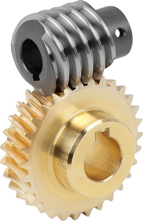
Can you explain the concept of worm and worm wheel in a worm gear?
In a worm gear system, the worm and worm wheel are the two primary components that work together to transmit motion and power. Here’s an explanation of the concept:
Worm:
The worm is a cylindrical shaft with a helical thread wrapped around it. It resembles a screw with a spiral groove. The helical thread is called the worm’s thread or worm thread. The worm is the driving component in the worm gear system.
When the worm rotates, the helical thread engages with the teeth of the worm wheel, causing the worm wheel to rotate. The angle of the helical thread creates a wedging action against the teeth of the worm wheel, resulting in a high gear reduction ratio.
One important characteristic of the worm is its self-locking nature. Due to the angle of the helical thread, the worm can drive the worm wheel, but the reverse is not true. The self-locking feature prevents the worm wheel from backdriving the worm, providing a mechanical brake or holding position in the system.
The worm can be made from various materials such as steel, bronze, or even plastics, depending on the application requirements. It is often mounted on a shaft and supported by bearings for smooth rotation.
Worm Wheel:
The worm wheel, also known as the worm gear, is the driven component in the worm gear system. It is a gear with teeth that mesh with the helical thread of the worm. The teeth on the worm wheel are typically helical and cut to match the angle and pitch of the worm’s thread.
As the worm rotates, its helical thread engages with the teeth of the worm wheel, causing the worm wheel to rotate. The rotation of the worm wheel is in the same direction as the worm’s rotation, but the speed is significantly reduced due to the high gear reduction ratio of the worm gear system.
The worm wheel is usually larger in diameter compared to the worm, allowing for a higher gear reduction ratio. It can be made from materials such as steel, bronze, or cast iron, depending on the application’s torque and durability requirements.
Together, the worm and worm wheel form a compact and efficient gear system that provides high gear reduction and self-locking capabilities. They are commonly used in various applications where precise motion control, high torque, and compactness are required, such as elevators, steering systems, and machine tools.
editor by CX 2024-01-11
China high quality Transmission Custom Precision Machine Shaft Metal Pinion Wheel Spiral Helical Bevel Gear gear ratio calculator
Product Description
Product Description
Transmission Custom Precision Machine shaft Metal Pinion Wheel Spiral Helical Bevel Gear
| Item | Customized machined machining gears | |
| Process | CNC machining,CNC milling, cnc lathe machining | |
| material | steel, stainless steel, carbon steel,brass,C360 brass copper, aluminum 7075,7068 brass,C360 brass copper, aluminum Nylon, PA66, NYLON , ABS, PP,PC,PE,POM,PVC,PU,TPR,TPE,TPU,PA,PET,HDPE,PMMA etc | |
| Quality Control | ISO9001 and ISO14001 | |
| Dimension bore tolerances | -/+0.01mm | |
| Quality standard | AGMA, JIS, DIN | |
| Surface treatment | Blackening, plated, anodizing, hard anodizing etc | |
| Gear hardness | 30 to 60 H.R.C | |
| Size/Color | Gears and parts dimensions are according to drawings from customer, and colors are customized | |
| Surface treatment | Polished or matte surface, painting, texture, vacuum aluminizing and can be stamped with logo etc. | |
| Dimensions Tolerance | ±0.01mm or more precise | |
| Samples confirmation and approval | samples shipped for confirmation and shipping cost paid by customers | |
| Package | Inner clear plastic bag/outside carton/wooden pallets/ or any other special package as per customer’s requirements. | |
| Delivery Time | Total takes 2~~8weeks usually | |
| Shipping |
Usual FEDEX, UPS, DHL, TNT, EMS or base on customer’s requirement. |
Production management:
1. The workers are trained to inspect the gears and notice any defect in production in time.
2. QC will check 1pcs every 100pcs in CNC machining, and gears will meet all dimension tolerances.
3. Gears will be inspected at every step, and gears will be inspected before shipment, and all inspection records will be kept in our factory for 3 years.
4. Our sales will send you pictures at every gears production steps, and you will know the detailed production status, and you can notice any possibility of mistake, for our sales, QC and workers are keeping close watch on all production.
5. You will feel us working very carefully to assure the quality and easy to work with,
6. we cherish every inquiry, every opportunity to make gears and parts and cherish every customer.
QUALITY CONTROL PROCESS:
1) Inspecting the raw material –IQC)
2) Checking the details before the production line operated
3) Have full inspection and routing inspection during mass production—In process quality control (IPQC)
4) Checking the gears after production finished—- (FQC)
5) Checking the gears after they are finished—–Outgoing quality control (OQC)
Service:
1. Molds designs as per customers’ gears drawing;
2. Submitting molds drawings to customers to review and confirm before mols production.
3. Providing samples with whole dimensions and cosmetic inspection report, material certification to customers.
4. Providing inspection report of important dimensions and cosmetic in batches parts.
Packing and shipment:
1. Gears are well and carefully packed in PP bags in CTNS, strong enough for express shipping, air shipment or sea shipment.
2. Air shipment, sea shipment or shipment by DHL, UPS, FedEx or TNT are availabe.
3. Trade terms: EXW, FOB HangZhou, or CIF
4. All shippings will be carefully arranged and will reach your places fast and safely.
FAQ
Q1: How to guarantee the Quality of gears and parts?
We are ISO 9001:2008 certified factory and we have the integrated system for industrial parts quality control. We have IQC (incoming quality control),
IPQCS (in process quality control section), FQC (final quality control) and OQC (out-going quality control) to control each process of industrial parts prodution.
Q2: What are the Advantage of your gears and parts?
Our advantage is the competitive and reasonable prices, fast delivery and high quality. Our eployees are responsible-oriented, friendly-oriented,and dilient-oriented.
Our industrial parts products are featured by strict tolerance, smooth finish and long-life performance.
Q3: what are our machining equipments?
Our machining equipments include plasticn injection machinies, CNC milling machines, CNC turning machines, stamping machines, hobbing machines, automatic lathe machines, tapping machines, grinding machines, cutting machines and so on.
Q4: What shipping ways do you use?
Generally, we will use UPS DHL or FEDEX and sea shipping
5: What materials can you process?
For plastic injection gears and parts, the materials are Nylon, PA66, NYLON with 30% glass fibre, ABS, PP,PC,PE,POM,PVC,PU,TPR,TPE,TPU,PA,PET,HDPE,PMMA etc.
For metal and machining gears and parts, the materials are brass, bronze, copper, stainless steel, steel, aluminum, titanium plastic etc.
Q6: How long is the Delivery for Your gears and parts?
Generally , it will take us 15 working days for injection or machining, and we will try to shorten our lead time.
/* March 10, 2571 17:59:20 */!function(){function s(e,r){var a,o={};try{e&&e.split(“,”).forEach(function(e,t){e&&(a=e.match(/(.*?):(.*)$/))&&1
| Application: | Motor, Electric Cars, Machinery, Toy, Agricultural Machinery, Car |
|---|---|
| Hardness: | Hardened Tooth Surface |
| Gear Position: | External Gear |
| Manufacturing Method: | Cut Gear |
| Toothed Portion Shape: | Curved Gear |
| Material: | Stainless Steel |
| Samples: |
US$ 10/Piece
1 Piece(Min.Order) | |
|---|
| Customization: |
Available
| Customized Request |
|---|
What is the lifespan of a typical worm gear?
The lifespan of a typical worm gear can vary depending on several factors, including the quality of materials, design, operating conditions, maintenance practices, and the specific application. Here’s a detailed explanation of the factors that influence the lifespan of a worm gear:
1. Quality of materials: The choice of materials used in the construction of the worm gear greatly impacts its lifespan. High-quality materials, such as hardened steel or bronze, offer better durability, wear resistance, and overall longevity compared to lower-quality materials. The selection of appropriate materials based on the application requirements is crucial for achieving a longer lifespan.
2. Design considerations: The design of the worm gear, including factors such as tooth profile, size, and load distribution, can influence its lifespan. Well-designed worm gears with optimized tooth geometry and proper load-carrying capacity tend to have longer lifespans. Additionally, features like lubrication systems and anti-backlash mechanisms can also contribute to improved durability and extended lifespan.
3. Operating conditions: The operating conditions under which the worm gear operates play a significant role in determining its lifespan. Factors such as load magnitude, speed, temperature, and environmental conditions can affect the wear and fatigue characteristics of the gear. Properly matching the worm gear to the application requirements and ensuring that it operates within specified limits can help prolong its lifespan.
4. Maintenance practices: Regular maintenance and proper lubrication are essential for maximizing the lifespan of a worm gear. Adequate lubrication helps reduce friction, wear, and heat generation, thereby extending the gear’s life. Regular inspections, lubricant replenishment, and timely replacement of worn or damaged components are important maintenance practices that can positively impact the lifespan of the worm gear.
5. Application-specific factors: The specific application in which the worm gear is used can also influence its lifespan. Factors such as operating cycles, torque levels, shock loads, and duty cycles vary between applications and can impact the wear and fatigue experienced by the gear. Understanding the unique requirements and demands of the application and selecting a worm gear that is appropriately rated and designed for those conditions can contribute to a longer lifespan.
Given the variations in materials, designs, operating conditions, and maintenance practices, it is challenging to provide a specific lifespan for a typical worm gear. However, with proper selection, installation, and maintenance, worm gears can have a lifespan ranging from several years to decades, depending on the factors mentioned above.
It is worth noting that monitoring the performance of the worm gear through regular inspections and addressing any signs of wear, damage, or excessive backlash can help identify potential issues early and extend the gear’s lifespan. Additionally, following the manufacturer’s guidelines and recommendations regarding maintenance intervals, lubrication types, and operating limits can significantly contribute to maximizing the lifespan of a worm gear.

What are the environmental considerations when using worm gears?
When using worm gears, there are several environmental considerations to keep in mind. Here’s a detailed explanation of these considerations:
- Lubrication: Proper lubrication is essential for the efficient and reliable operation of worm gears. Lubricants help reduce friction and wear between the gear teeth, resulting in improved efficiency and extended gear life. When selecting lubricants, it is important to consider their environmental impact. Environmentally friendly lubricants, such as biodegradable or synthetic lubricants with low toxicity, can be used to minimize the potential harm to the environment in case of leakage or accidental spills.
- Leakage and contamination: Worm gear systems are susceptible to lubricant leakage, which can cause environmental pollution. It is important to ensure that the gear housing is properly sealed to prevent lubricant leakage into the environment. Regular inspections and maintenance should be carried out to detect and repair any leaks promptly. Additionally, measures should be taken to prevent contaminants such as dust, dirt, and water from entering the gear system, as they can degrade the lubricant and affect the gear performance.
- Energy efficiency: Worm gears, like any mechanical power transmission system, consume energy during operation. It is important to consider energy efficiency when selecting and designing worm gear systems. Optimal gear design, proper gear selection, and efficient lubrication practices can contribute to reducing energy consumption and minimizing the environmental impact associated with energy use.
- Noise and vibration: Worm gears can generate noise and vibration during operation. Excessive noise can contribute to noise pollution, while high vibration levels can impact the surrounding equipment and structures. To mitigate these effects, it is important to design and manufacture worm gears with low noise and vibration characteristics. This can involve careful gear design, proper lubrication, and the use of vibration-damping materials or mechanisms.
- End-of-life considerations: At the end of their service life, worm gear components may need to be replaced or recycled. Disposal of worn-out gears should be done in accordance with applicable environmental regulations. Whenever possible, recycling or reusing gear components can help reduce waste and minimize the environmental impact associated with the disposal of gear materials.
- Environmental regulations: Compliance with environmental regulations and standards is crucial when using worm gears. Different regions may have specific regulations governing the use and disposal of lubricants, materials, and manufacturing processes associated with gear systems. It is important to stay informed about these regulations and ensure compliance to avoid any adverse environmental impact and legal consequences.
By considering these environmental factors, it is possible to minimize the ecological footprint of worm gear systems and promote sustainable practices in their use and maintenance. This includes selecting environmentally friendly lubricants, implementing proper sealing and maintenance procedures, optimizing energy efficiency, and adhering to relevant environmental regulations.
How does a worm gear differ from other types of gears?
A worm gear differs from other types of gears in several ways. Here are the key differences:
- Gear Configuration: A worm gear consists of a threaded worm and a mating gear, known as the worm wheel or worm gear. The worm has a helical thread that meshes with the teeth of the worm wheel. In contrast, other types of gears, such as spur gears, bevel gears, and helical gears, have parallel or intersecting axes of rotation.
- Gear Ratio: Worm gears provide high gear reduction ratios compared to other types of gears. The ratio is determined by the number of teeth on the worm wheel and the number of threads on the worm. This high reduction ratio allows worm gears to transmit more torque while maintaining a compact size.
- Direction of Rotation: In a worm gear system, the worm can drive the worm wheel, but the reverse is not true. This is due to the self-locking nature of worm gears. The angle of the worm’s helical thread creates a wedging action that prevents the worm wheel from backdriving the worm. This characteristic makes worm gears suitable for applications requiring a mechanical brake or holding position.
- Efficiency: Worm gears typically have lower efficiency compared to other types of gears. This is primarily due to the sliding action between the worm’s threads and the worm wheel’s teeth, which leads to higher friction and energy losses. Therefore, worm gears are not ideal for applications that require high efficiency or continuous, high-speed operation.
- Lubrication: Worm gears require proper lubrication to reduce friction and wear. The sliding action between the worm and the worm wheel generates heat, which can affect the performance and lifespan of the gear system. Lubricants help to dissipate heat and provide a protective film between the mating surfaces, reducing friction and extending the gear’s life.
- Applications: Worm gears are commonly used in applications that require high gear reduction, compact size, and self-locking capabilities. They are found in various industries, including elevators, automotive steering systems, machine tools, robotics, and winding mechanisms.
Overall, the unique design and characteristics of worm gears make them suitable for specific applications where high torque, compactness, and self-locking features are essential, even though they may have lower efficiency compared to other types of gears.
editor by CX 2024-01-11
China Custom Customized Machining Tractor/Planet/Planetary/Epicyclic CZPT Gear worm gear motor
Product Description
Customized Machining Tractor/Planet/Planetary/Epicyclic CHINAMFG Gear
Product Description
Major Products:
spur gear; worm gear; bevel gear; planetary gear; gear; metal gear; cycle gear; pinion gear; gear
manufacturing; helical gear; custom gear; spiral bevel gear; rack and pinion gear; mechanical
gears; transmission gears; rack gear; spiral gear; work gear; gear reducer; richmond gear;
hypoid gear; gear wheels; pulleys and gears; motive gear; gear teeth; truck gear; gear system;
involute gear.
|
Material |
Steel:Carbon steel/ Mild steel/ Cold roll steel/ Hot roll steel |
|
Surface Treatment |
Zinc plating, Powder, Passivation, Sand blasting, Brushing & ploshing etc. |
|
Processing Equipment |
Large laser cutter Bending machine Plasma cutting machine Punching machine Wire cutter CNC machining center CNC lathe Automatic lathe machine Milling machine Drilling machine |
|
Drawing Format |
pdf/.igs./.stp/x_t. etc. |
|
Drawing Format |
EXW, FOB, CIF |
|
Packing of Sheet Metal Stamping |
PE bag+carton box or other custom packaging |
|
Applications |
Auto Parts/Motocycle parts/Contruction Parts/Furniture Parts/Electronic Parts |
PRODUCT DESCRIPOTION
1. CHINAMFG wheel and pinion gears and spiral bevel gears for automobile rear axle, truck, tractor
front/rear axle and tool.
2. Raw material: 20CrMni \22CrMo \8620 \SCM420
Processing: Forging, normalizing, rough, machining, fine finishi, carburizing, tempering,
annealing, accurate grinding, matching and testing, packing.
3. The tooth surface is finished by lapping machine, the color will be silver gray
4. Hardness about surface: HRC58-62, internal: HRC35-40.
5. We can process gears according to customers drawing and samples.
Inspections:
3D instruments, 2D instruments, Projectors, Height Gauges, Inner diameter dial indicators, Dial gaues,
Thread and Pin gauges, Digital calipers,Micro calipers, Thickness testers, Hardness testers Roughness
testers, etc.( Detection accuracy to 0.001 millimetre )
| Mininum of Quantity | 100 Piece/Pieces |
| Unit Weight | 0.5kg~300kg |
| Price | FOB HangZhou,China,USD1.5~1.9 |
| Packing Details | Paper Box in Wooden Pallet |
| Delivery Time | One month |
| Payment Terms | L/C, T/T |
| Machining | CNC or |
| Supply Capacity | 50 Metric Tons per Month |
| Standard | DIN,ASTM,GOST,B |
Packaging & Shipping
Packing:
1: Shrink film+ bulk loading
2: Shrink film +Carton box + Pallet/ wooden case
3: PP + Wooden case
4: As per customers’ requirements or negotiated
FAQ
Q1: How can I get cnc spare parts sample?
1. Sample fee will be free if we have in stock, you just need to pay the shipping cost is OK.
2. The sample of your own design needs to pay for the mold set up charge. Samples production takes
5-7 working days after set up charge received & size drawing approval.
Q2: How to pay for the order?
There are 4 options to pay the order: Bank Transfer; Western Union; Paypal; Payoneer. Kindly choose
the most suitable way for you to arrange it.
Q3: What is the shipping method?
The samples were sent out by international airway express company like DHL, UPS, FedEx, TNT.
Usually takes around 5-7 working days (door to door service). We arrange goods shipment via sea
or air.
Q4: Can you give me help if my products are very urgent?
Yes, We can work overtime and add a few machines to produce these products if you need it urgently.
Q5: I want to keep our design in secret, can we CHINAMFG NDA?
Sure, we will not display any customers’ design or show to other people, we can CHINAMFG NDA.
You can look through our website to find your interest or email your any questions through
below approach! We will reply to you within 12 hours.
/* March 10, 2571 17:59:20 */!function(){function s(e,r){var a,o={};try{e&&e.split(“,”).forEach(function(e,t){e&&(a=e.match(/(.*?):(.*)$/))&&1
| Application: | Motor, Electric Cars, Motorcycle, Machinery, Marine, Agricultural Machinery |
|---|---|
| Hardness: | Hardened Tooth Surface |
| Gear Position: | Internal Gear |
| Samples: |
US$ 4/Piece
1 Piece(Min.Order) | Order Sample machining gears
|
|---|
| Customization: |
Available
| Customized Request |
|---|
.shipping-cost-tm .tm-status-off{background: none;padding:0;color: #1470cc}
|
Shipping Cost:
Estimated freight per unit. |
about shipping cost and estimated delivery time. |
|---|
| Payment Method: |
|
|---|---|
|
Initial Payment Full Payment |
| Currency: | US$ |
|---|
| Return&refunds: | You can apply for a refund up to 30 days after receipt of the products. |
|---|

How do you prevent backlash and gear play in a worm gear mechanism?
Preventing backlash and gear play is essential for maintaining the accuracy and performance of a worm gear mechanism. Here’s a detailed explanation of how to prevent backlash and gear play in a worm gear mechanism:
Backlash refers to the play or clearance between the teeth of the worm and the worm wheel in a worm gear mechanism. It can result in inaccuracies, positioning errors, and reduced efficiency. Here are some measures to prevent or minimize backlash and gear play:
- Precision manufacturing: Accurate and precise manufacturing of the worm and worm wheel is crucial to minimize backlash. High-quality machining techniques, such as grinding, can be employed to achieve precise tooth profiles and minimize any gaps between the teeth. Careful attention to the design and manufacturing tolerances can help reduce backlash.
- Tight meshing clearance: Proper adjustment of the meshing clearance between the worm and the worm wheel can help minimize backlash. The meshing clearance should be set as small as possible without causing interference or excessive friction. Close clearance ensures a tighter fit between the teeth, reducing the amount of play or backlash.
- Anti-backlash mechanisms: Anti-backlash mechanisms can be incorporated into the worm gear system to reduce or eliminate backlash. These mechanisms typically consist of spring-loaded components or adjustable devices that help compensate for any clearance between the teeth. They apply a constant pressure to keep the teeth engaged tightly, reducing the effects of backlash.
- Preload: Applying a preload to the worm gear system can help minimize backlash. Preload involves applying a slight compressive force or tension to the components, ensuring they remain engaged and eliminating any clearance. However, it is important to apply the appropriate preload to avoid excessive friction and wear.
- Lubrication: Proper lubrication is crucial for minimizing backlash and reducing gear play. Lubricants with suitable viscosity and properties should be used to ensure smooth and consistent operation of the worm gear mechanism. Good lubrication helps reduce friction, wear, and any potential clearance that can contribute to backlash.
- Regular maintenance: Regular inspection and maintenance of the worm gear mechanism can help detect and address any developing backlash or gear play. Routine checks can identify signs of wear, misalignment, or improper lubrication, allowing for timely adjustments or replacements to minimize backlash and maintain optimal performance.
It’s important to note that completely eliminating backlash in a worm gear mechanism may not always be possible or desirable. Some applications require a certain level of backlash to accommodate thermal expansion, compensate for positional errors, or allow for smooth operation. The acceptable level of backlash depends on the specific requirements of the application.
When implementing measures to prevent backlash and gear play, it is crucial to strike a balance between minimizing backlash and ensuring smooth, reliable operation. The specific techniques and approaches used to minimize backlash may vary depending on the design, manufacturing, and application requirements of the worm gear mechanism.
What are the environmental considerations when using worm gears?
When using worm gears, there are several environmental considerations to keep in mind. Here’s a detailed explanation of these considerations:
- Lubrication: Proper lubrication is essential for the efficient and reliable operation of worm gears. Lubricants help reduce friction and wear between the gear teeth, resulting in improved efficiency and extended gear life. When selecting lubricants, it is important to consider their environmental impact. Environmentally friendly lubricants, such as biodegradable or synthetic lubricants with low toxicity, can be used to minimize the potential harm to the environment in case of leakage or accidental spills.
- Leakage and contamination: Worm gear systems are susceptible to lubricant leakage, which can cause environmental pollution. It is important to ensure that the gear housing is properly sealed to prevent lubricant leakage into the environment. Regular inspections and maintenance should be carried out to detect and repair any leaks promptly. Additionally, measures should be taken to prevent contaminants such as dust, dirt, and water from entering the gear system, as they can degrade the lubricant and affect the gear performance.
- Energy efficiency: Worm gears, like any mechanical power transmission system, consume energy during operation. It is important to consider energy efficiency when selecting and designing worm gear systems. Optimal gear design, proper gear selection, and efficient lubrication practices can contribute to reducing energy consumption and minimizing the environmental impact associated with energy use.
- Noise and vibration: Worm gears can generate noise and vibration during operation. Excessive noise can contribute to noise pollution, while high vibration levels can impact the surrounding equipment and structures. To mitigate these effects, it is important to design and manufacture worm gears with low noise and vibration characteristics. This can involve careful gear design, proper lubrication, and the use of vibration-damping materials or mechanisms.
- End-of-life considerations: At the end of their service life, worm gear components may need to be replaced or recycled. Disposal of worn-out gears should be done in accordance with applicable environmental regulations. Whenever possible, recycling or reusing gear components can help reduce waste and minimize the environmental impact associated with the disposal of gear materials.
- Environmental regulations: Compliance with environmental regulations and standards is crucial when using worm gears. Different regions may have specific regulations governing the use and disposal of lubricants, materials, and manufacturing processes associated with gear systems. It is important to stay informed about these regulations and ensure compliance to avoid any adverse environmental impact and legal consequences.
By considering these environmental factors, it is possible to minimize the ecological footprint of worm gear systems and promote sustainable practices in their use and maintenance. This includes selecting environmentally friendly lubricants, implementing proper sealing and maintenance procedures, optimizing energy efficiency, and adhering to relevant environmental regulations.

How do you calculate the gear ratio of a worm gear?
Calculating the gear ratio of a worm gear involves determining the number of teeth on the worm wheel and the pitch diameter of both the worm and worm wheel. Here’s the step-by-step process:
- Determine the number of teeth on the worm wheel (Zworm wheel). This information can usually be obtained from the gear specifications or by physically counting the teeth.
- Measure or determine the pitch diameter of the worm (Dworm) and the worm wheel (Dworm wheel). The pitch diameter is the diameter of the reference circle that corresponds to the pitch of the gear. It can be measured directly or calculated using the formula: Dpitch = (Z / P), where Z is the number of teeth and P is the circular pitch (the distance between corresponding points on adjacent teeth).
- Calculate the gear ratio (GR) using the following formula: GR = (Zworm wheel / Zworm) * (Dworm wheel / Dworm).
The gear ratio represents the speed reduction and torque multiplication provided by the worm gear system. A higher gear ratio indicates a greater reduction in speed and higher torque output, while a lower gear ratio results in less speed reduction and lower torque output.
It’s worth noting that in worm gear systems, the gear ratio is also influenced by the helix angle and lead angle of the worm. These angles determine the rate of rotation and axial movement per revolution of the worm. Therefore, when selecting a worm gear, it’s important to consider not only the gear ratio but also the specific design parameters and performance characteristics of the worm and worm wheel.
editor by CX 2024-01-10
China Standard Professional Factory Supply Metal Gears Manufacturer Steel Spur Gear bevel gearbox
Product Description
|
Product category |
Super gear, Ring gear, Cylindrical gear, Helical gear , Bevel gear, Pinion gear, Rack gear, Worm gear,Tooth shaft,Flange etc. |
|
Material |
Stainless steel, steel ,steel alloys,copper etc. |
|
Specification |
According To Drawings Or Samples Customized |
|
Tolerance |
As per drawing (+/-0.01~+/-0.03mm) |
|
Teeth Width |
10-150 teeth or customized |
|
Machining process |
CNC turning, CNC milling, Drilling, Grinding, Wire-EDM cutting ,Stamping, |
|
Surface treatment |
Anodizing,Sand blasting,Painting,Powder coating,Plating,Brushing,Polishing,Laser Engraving |
|
Application |
Used in bicycles, motorcycles, automobiles, motors, engines, electric appliance,automated mechanical systems,other industries etc. |
|
MOQ |
100~1000 pieces ,According to the size of the product. |
|
Sample |
Available |
|
Lead Time |
20-60Days Depends On Quantities and complexity |
|
Payment Term |
T/T 30% deposit and balanced 70% to pay before shipment or to be negotiated |
|
Port Of Loading |
ZheJiang |
ZheZheJiang nlead Precision Co., Ltd. which focuses on CNC machining, including milling, turning, auto-lathe turning,holing,grinding, heat treatment from raw materials of bars, tube, extruded profiles, blanks of cold forging & hot forging, aluminum die casting.
We provide one-stop service, from professional design analysis, to free quote, fast prototype, IATF16949 & ISO14001 standard manufacturing, to safe shipping and great after-sales services.During 16 years, we have win lots of trust in the global market, most of them come from North America and Europe.
Now you may have steady customers, and hope you can keep us in the archives to get more market news.
Sunlead produce all kinds of machining parts according to customer’s drawing, we can produces stainless steel Turned parts,carbon steel Turned parts, aluminum turned parts,brass & copper turned parts. Please feel free to send inquiry to us, and our professional sales manager will get back to you ASAP!
FAQ
Q1: Are you a factory or a trading company?
A1: We are a OEM factory located in ZheJiang , China.which have more than 15 years experience on making cnc machining parts and plastic injection molds.
Q2: How can I get a quote?
A2: Detailed drawings (PDF/STEP/IGS/DWG…) with material, quantity and surface treatment information.
Q3: How much time do you need to quote?
A3: Usually a quotation for a product is sent in 24 hours after we receive enquiry with all the necessary detatils
Q4: Can I get a quote without drawings?
Sure, we appreciate to receive your samples, pictures or drafts with detailed dimensions for accurate quotation.
Q5: How can I get a sample for quality check?
A5: After quotation, if needed, you can ask for samples to check quality. We are willing to provide with sample for quality and function testing. sample fee is needed, will be returned when mass production if possible.
Q7: How do you control the quality?
A7: (1) Material inspection–Check the material surface and roughly dimension.
(2) Production first inspection–To ensure the critical dimension in mass production.
(3) Sampling inspection–Check the quality before sending to the warehouse.
(4) Pre-shipment inspection–100% inspected by QC assistants before shipment.
Q8: What will you do if we receive poor quality parts?
A8: Please kindly send us the pictures, our engineers will find the solutions and remake them for you asap.
/* March 10, 2571 17:59:20 */!function(){function s(e,r){var a,o={};try{e&&e.split(“,”).forEach(function(e,t){e&&(a=e.match(/(.*?):(.*)$/))&&1
| Application: | Motor, Electric Cars, Motorcycle |
|---|---|
| Hardness: | Hardened Tooth Surface |
| Gear Position: | External Gear |
| Samples: |
US$ 1.2/Piece
1 Piece(Min.Order) | Order Sample |
|---|
| Customization: |
Available
| Customized Request |
|---|
.shipping-cost-tm .tm-status-off{background: none;padding:0;color: #1470cc}
| Shipping Cost:
Estimated freight per unit. |
about shipping cost and estimated delivery time. |
|---|
| Payment Method: |
|
|---|---|
|
Initial Payment Full Payment |
| Currency: | US$ |
|---|
| Return&refunds: | You can apply for a refund up to 30 days after receipt of the products. |
|---|
What is the lifespan of a typical worm gear?
The lifespan of a typical worm gear can vary depending on several factors, including the quality of materials, design, operating conditions, maintenance practices, and the specific application. Here’s a detailed explanation of the factors that influence the lifespan of a worm gear:
1. Quality of materials: The choice of materials used in the construction of the worm gear greatly impacts its lifespan. High-quality materials, such as hardened steel or bronze, offer better durability, wear resistance, and overall longevity compared to lower-quality materials. The selection of appropriate materials based on the application requirements is crucial for achieving a longer lifespan.
2. Design considerations: The design of the worm gear, including factors such as tooth profile, size, and load distribution, can influence its lifespan. Well-designed worm gears with optimized tooth geometry and proper load-carrying capacity tend to have longer lifespans. Additionally, features like lubrication systems and anti-backlash mechanisms can also contribute to improved durability and extended lifespan.
3. Operating conditions: The operating conditions under which the worm gear operates play a significant role in determining its lifespan. Factors such as load magnitude, speed, temperature, and environmental conditions can affect the wear and fatigue characteristics of the gear. Properly matching the worm gear to the application requirements and ensuring that it operates within specified limits can help prolong its lifespan.
4. Maintenance practices: Regular maintenance and proper lubrication are essential for maximizing the lifespan of a worm gear. Adequate lubrication helps reduce friction, wear, and heat generation, thereby extending the gear’s life. Regular inspections, lubricant replenishment, and timely replacement of worn or damaged components are important maintenance practices that can positively impact the lifespan of the worm gear.
5. Application-specific factors: The specific application in which the worm gear is used can also influence its lifespan. Factors such as operating cycles, torque levels, shock loads, and duty cycles vary between applications and can impact the wear and fatigue experienced by the gear. Understanding the unique requirements and demands of the application and selecting a worm gear that is appropriately rated and designed for those conditions can contribute to a longer lifespan.
Given the variations in materials, designs, operating conditions, and maintenance practices, it is challenging to provide a specific lifespan for a typical worm gear. However, with proper selection, installation, and maintenance, worm gears can have a lifespan ranging from several years to decades, depending on the factors mentioned above.
It is worth noting that monitoring the performance of the worm gear through regular inspections and addressing any signs of wear, damage, or excessive backlash can help identify potential issues early and extend the gear’s lifespan. Additionally, following the manufacturer’s guidelines and recommendations regarding maintenance intervals, lubrication types, and operating limits can significantly contribute to maximizing the lifespan of a worm gear.
What are the environmental considerations when using worm gears?
When using worm gears, there are several environmental considerations to keep in mind. Here’s a detailed explanation of these considerations:
- Lubrication: Proper lubrication is essential for the efficient and reliable operation of worm gears. Lubricants help reduce friction and wear between the gear teeth, resulting in improved efficiency and extended gear life. When selecting lubricants, it is important to consider their environmental impact. Environmentally friendly lubricants, such as biodegradable or synthetic lubricants with low toxicity, can be used to minimize the potential harm to the environment in case of leakage or accidental spills.
- Leakage and contamination: Worm gear systems are susceptible to lubricant leakage, which can cause environmental pollution. It is important to ensure that the gear housing is properly sealed to prevent lubricant leakage into the environment. Regular inspections and maintenance should be carried out to detect and repair any leaks promptly. Additionally, measures should be taken to prevent contaminants such as dust, dirt, and water from entering the gear system, as they can degrade the lubricant and affect the gear performance.
- Energy efficiency: Worm gears, like any mechanical power transmission system, consume energy during operation. It is important to consider energy efficiency when selecting and designing worm gear systems. Optimal gear design, proper gear selection, and efficient lubrication practices can contribute to reducing energy consumption and minimizing the environmental impact associated with energy use.
- Noise and vibration: Worm gears can generate noise and vibration during operation. Excessive noise can contribute to noise pollution, while high vibration levels can impact the surrounding equipment and structures. To mitigate these effects, it is important to design and manufacture worm gears with low noise and vibration characteristics. This can involve careful gear design, proper lubrication, and the use of vibration-damping materials or mechanisms.
- End-of-life considerations: At the end of their service life, worm gear components may need to be replaced or recycled. Disposal of worn-out gears should be done in accordance with applicable environmental regulations. Whenever possible, recycling or reusing gear components can help reduce waste and minimize the environmental impact associated with the disposal of gear materials.
- Environmental regulations: Compliance with environmental regulations and standards is crucial when using worm gears. Different regions may have specific regulations governing the use and disposal of lubricants, materials, and manufacturing processes associated with gear systems. It is important to stay informed about these regulations and ensure compliance to avoid any adverse environmental impact and legal consequences.
By considering these environmental factors, it is possible to minimize the ecological footprint of worm gear systems and promote sustainable practices in their use and maintenance. This includes selecting environmentally friendly lubricants, implementing proper sealing and maintenance procedures, optimizing energy efficiency, and adhering to relevant environmental regulations.
Can you explain the concept of worm and worm wheel in a worm gear?
In a worm gear system, the worm and worm wheel are the two primary components that work together to transmit motion and power. Here’s an explanation of the concept:
Worm:
The worm is a cylindrical shaft with a helical thread wrapped around it. It resembles a screw with a spiral groove. The helical thread is called the worm’s thread or worm thread. The worm is the driving component in the worm gear system.
When the worm rotates, the helical thread engages with the teeth of the worm wheel, causing the worm wheel to rotate. The angle of the helical thread creates a wedging action against the teeth of the worm wheel, resulting in a high gear reduction ratio.
One important characteristic of the worm is its self-locking nature. Due to the angle of the helical thread, the worm can drive the worm wheel, but the reverse is not true. The self-locking feature prevents the worm wheel from backdriving the worm, providing a mechanical brake or holding position in the system.
The worm can be made from various materials such as steel, bronze, or even plastics, depending on the application requirements. It is often mounted on a shaft and supported by bearings for smooth rotation.
Worm Wheel:
The worm wheel, also known as the worm gear, is the driven component in the worm gear system. It is a gear with teeth that mesh with the helical thread of the worm. The teeth on the worm wheel are typically helical and cut to match the angle and pitch of the worm’s thread.
As the worm rotates, its helical thread engages with the teeth of the worm wheel, causing the worm wheel to rotate. The rotation of the worm wheel is in the same direction as the worm’s rotation, but the speed is significantly reduced due to the high gear reduction ratio of the worm gear system.
The worm wheel is usually larger in diameter compared to the worm, allowing for a higher gear reduction ratio. It can be made from materials such as steel, bronze, or cast iron, depending on the application’s torque and durability requirements.
Together, the worm and worm wheel form a compact and efficient gear system that provides high gear reduction and self-locking capabilities. They are commonly used in various applications where precise motion control, high torque, and compactness are required, such as elevators, steering systems, and machine tools.
editor by CX 2024-01-10
China Custom Customized Spur Gear, Helical Gear, Herringbone Gear, Helical Gear, Worm Gear, Spiral Bevel Gear, Transmission Gear, Ring Gear bevel gear set
Product Description
1) According to the different strength and performance, we choose the steel with strong compression;
2) Using Germany professional software and our professional engineers to design products with more reasonable size and better performance; 3) We can custom ize our products according to the needs of our customers,Therefore, the optimal performance of the gear can be exerted under different working conditions;
4) Quality assurance in every step to ensure product quality is controllable.
Product Paramenters
|
DRIVEN GEAR |
NUMBER OF TEETH |
24 |
|
MODULE |
10.345 |
|
|
LENTH |
302 |
|
|
OUTER DIAMETER |
ø249 |
|
|
DIRECTION OF SPIRAL |
R |
|
|
ACCURACY OF SPLINE |
M55*1.5-6h |
|
|
NUMBER OF SPLINE |
31 |
|
DRIVEN GEAR |
NUMBER OF TEETH |
29 |
||||||||||||||||||||||||||||||||||||||||||||||||||||||||||||||||||||||||||||||||||||||||||||||||||||||||||||||||||||||||||||||||||||||||||||||||||||||||||||||||||||||
|
OUTER DIAMETER |
ø3 square meter, with building area of 72,000 square meters. More than 500 employees work in our company. Certification & honors Packaging & Shipping Packaging Detail:standard package(carton ,wooden pallet).
Cooperative customers HangZhou CHINAMFG Gear Co., Ltd. adheres to the concept of “people-oriented, prosper with science and technology; create high-quality products, contribute to the society; turn friendship, and contribute sincerely”, and will strive to create world automotive axle spiral bevel gear products.
How does a worm gear impact the overall efficiency of a system?A worm gear has a significant impact on the overall efficiency of a system due to its unique design and mechanical characteristics. Here’s a detailed explanation of how a worm gear affects system efficiency: A worm gear consists of a worm (a screw-like gear) and a worm wheel (a cylindrical gear with teeth). When the worm rotates, it engages with the teeth of the worm wheel, causing the wheel to rotate. The main factors influencing the efficiency of a worm gear system are:
It’s important to note that while worm gears may have lower mechanical efficiency compared to some other gear types, they offer unique advantages such as high gear reduction ratios, compact design, and self-locking capabilities. The suitability of a worm gear system depends on the specific application requirements and the trade-offs between efficiency, torque transmission, and other factors. When designing or selecting a worm gear system, it is essential to consider the desired balance between efficiency, torque requirements, positional stability, and other performance factors to ensure optimal overall system efficiency.
Can worm gears be used in both horizontal and vertical orientations?Yes, worm gears can be used in both horizontal and vertical orientations. Here’s a detailed explanation of the suitability of worm gears for different orientations: 1. Horizontal Orientation: Worm gears are commonly used in horizontal orientations and are well-suited for such applications. In a horizontal configuration, the worm gear’s weight is primarily supported by the bearings and housing. The lubrication and load-carrying capabilities of the gear design are optimized for horizontal operation, allowing for efficient power transmission and torque generation. Horizontal worm gear applications include conveyor systems, mixers, mills, and many other industrial machinery setups. 2. Vertical Orientation: Worm gears can also be used in vertical orientations, although there are some additional considerations to address in such cases. In a vertical configuration, the weight of the worm gear exerts an axial force on the worm shaft, which can introduce additional load and affect the gear’s performance. To ensure proper operation in a vertical orientation, the following factors should be considered:
In summary, worm gears can be utilized in both horizontal and vertical orientations. However, certain considerations related to thrust load handling, lubrication, backlash control, bearing selection, and sealing should be taken into account for vertical applications. By addressing these factors appropriately, worm gears can effectively transmit power and torque, whether in horizontal or vertical configurations.
Understanding Worm Gears and Their OperationA worm gear is a type of mechanical gear that consists of a threaded screw-like component (called the worm) and a toothed wheel (called the worm gear). It is used to transmit motion between non-intersecting and perpendicular shafts. Here’s how it works: The worm, typically in the form of a cylindrical rod with a helical thread, meshes with the teeth of the worm gear. When the worm is rotated, its threads engage with the teeth of the worm gear, causing the gear to rotate. The direction of rotation of the worm gear is perpendicular to the axis of the worm. One significant feature of worm gears is their ability to provide high gear reduction ratios. The number of teeth on the worm gear relative to the number of threads on the worm determines the reduction ratio. This makes worm gears suitable for applications where high torque and low-speed rotation are required. Worm gears are commonly used in various mechanical systems, such as conveyor systems, lifts, automotive steering mechanisms, and more. Their unique design also provides a self-locking feature: when the system is not actively rotating the worm, the gear cannot easily backdrive the worm due to the angle of the threads, providing mechanical advantage and preventing reverse motion.
China Hot selling European Standard M1 M2 M3 M4 M5 M6 Custom CNC Machined Steel Helical Gear Rack and Pinion Gears M1.25 top gearProduct Description
Product Description GEAR CUTTER Product Parameters
Support customization. Welcome to consult. Detailed Photos Product Details Product Display
Support customization. Welcome to consult. Company Profile Company Profile Our factory topped the China Aviation Industry Corporation Tool centralized procurement list,our products are not only famous in domestic market, but also exported to dozens contries in the world.HangZhou Easy Joint Import&Export CO.,LTD. is a company integrating industry and trade, its factory was established in 1999, specializing in the production of carbide rotary cutting tools, our products are widely used in automotive, machining, aerospace and some other fields. Our Advantages High quality, Professional R&D center, Fast dispatch, Small order accepted, Global Export Expertise Certifications FAQ Q1: Are you a factory or trading company? Q2: How about the Shipping Method? Q3: How about the delivery date? Q4: How about the label and the logo?HSS And Tungsten Carbide Q5: How about the MOQ ?HSS And Tungsten Carbide /* March 10, 2571 17:59:20 */!function(){function s(e,r){var a,o={};try{e&&e.split(“,”).forEach(function(e,t){e&&(a=e.match(/(.*?):(.*)$/))&&1
.shipping-cost-tm .tm-status-off{background: none;padding:0;color: #1470cc}
Can worm gears be used in precision manufacturing equipment?Yes, worm gears can be used in precision manufacturing equipment. Here’s a detailed explanation of their use in precision manufacturing: 1. Precision Motion Control: Worm gears can provide precise motion control in manufacturing equipment. Their design allows for high gear ratios, which enables fine adjustments and precise positioning. This is particularly useful in applications where accurate and repeatable movement is required, such as CNC machines, robotic arms, and coordinate measuring machines (CMMs). 2. Load Holding and Backdriving Prevention: Worm gears have a self-locking characteristic, meaning they can hold loads in position without the need for additional brakes or clutches. This feature is advantageous in precision manufacturing equipment where holding a position is critical. The self-locking property also helps prevent backdriving, ensuring stability and accuracy during operation. 3. Compact Design: Worm gears have a compact design, which can be beneficial in space-constrained manufacturing equipment. Their worm and worm wheel configuration allows for a compact footprint, making them suitable for applications where size limitations exist. 4. High Torque Transmission: Worm gears can transmit high torque, making them suitable for heavy-duty precision manufacturing equipment. The meshing of the worm and worm wheel generates a large contact area, enabling efficient power transfer and load handling capabilities. 5. Reduced Noise and Vibration: Worm gears operate with a sliding motion rather than a rolling motion, resulting in reduced noise and vibration levels. This characteristic is advantageous in precision manufacturing equipment, as it helps maintain a quieter working environment and minimizes potential disturbances that could affect the precision of the manufacturing process. 6. Lubrication and Maintenance: Proper lubrication is crucial for the efficient and reliable operation of worm gears in precision manufacturing equipment. Lubricants help reduce friction and wear between the gear teeth, ensuring smooth and accurate motion. Regular maintenance and lubrication schedules should be followed to optimize gear performance and extend their service life. While worm gears offer several advantages in precision manufacturing equipment, it’s important to consider the specific requirements of the application. Factors such as gear ratio, efficiency, backlash, and operating conditions should be carefully evaluated to ensure that worm gears are the appropriate choice for achieving the desired precision and performance. Overall, worm gears can be successfully utilized in precision manufacturing equipment, providing precise motion control, load holding capabilities, compactness, and high torque transmission. When properly selected, installed, and maintained, worm gears can contribute to the accuracy, reliability, and efficiency of precision manufacturing processes.
How do you calculate the efficiency of a worm gear?Calculating the efficiency of a worm gear involves analyzing the power losses that occur during its operation. Here’s a detailed explanation of the process: The efficiency of a worm gear system is defined as the ratio of output power to input power. In other words, it represents the percentage of power that is successfully transmitted from the input (worm) to the output (worm wheel) without significant losses. To calculate the efficiency, the following steps are typically followed:
Efficiency = (Pout / Pin) * 100% The efficiency is expressed as a percentage, indicating the proportion of input power that is successfully transmitted to the output. A higher efficiency value indicates a more efficient gear system with fewer losses. It is important to note that the efficiency of a worm gear can vary depending on factors such as gear design, materials, lubrication, operating conditions, and manufacturing quality. Additionally, the efficiency may also change at different operating speeds or torque levels. Therefore, it is advisable to consider these factors and conduct efficiency calculations based on specific gear system parameters and operating conditions.
What is the purpose of a self-locking feature in a worm gear?A self-locking feature in a worm gear serves the purpose of preventing reverse motion or backdriving of the gear system. When a worm gear is self-locking, it means that the worm can rotate the worm wheel, but the reverse action is hindered or restricted, providing a mechanical holding or braking capability. This self-locking feature offers several advantages and is utilized in various applications. Here are the key purposes of the self-locking feature:
It’s important to note that not all worm gears are self-locking. The self-locking characteristic depends on the design parameters, specifically the helix angle of the worm’s thread. A higher helix angle increases the self-locking tendency, while a lower helix angle reduces or eliminates the self-locking effect. Therefore, when selecting a worm gear for an application that requires the self-locking feature, it is essential to consider the specific design parameters and ensure that the gear meets the necessary requirements.
China Professional Motor Boss Gear 1 Die 35-100 Teeth Inner Hole 6-12 Inner Hole 6/8/10/12 Top Hole Non Standard Sprocket Double Row Table Gear bevel gear setProduct Description
Motor boss gear 1 die 35-100 teeth inner hole 6-12 inner hole 6/8/10/12 top hole Non standard sprocket double row table gear Related products
Application What are some typical applications where double-row table gears are used?
/* March 10, 2571 17:59:20 */!function(){function s(e,r){var a,o={};try{e&&e.split(“,”).forEach(function(e,t){e&&(a=e.match(/(.*?):(.*)$/))&&1
Are worm gears suitable for high-torque applications?Worm gears are indeed well-suited for high-torque applications. Here’s a detailed explanation of why worm gears are suitable for high-torque applications: Worm gears are known for their ability to provide significant speed reduction and torque multiplication. They consist of a threaded cylindrical gear, called the worm, and a toothed wheel, called the worm wheel or worm gear. The interaction between the worm and the worm wheel enables the transmission of motion and torque. Here are the reasons why worm gears are suitable for high-torque applications:
It’s important to consider that while worm gears excel in high-torque applications, they may not be suitable for high-speed applications. The sliding contact between the worm and the worm wheel generates friction, which can lead to heat generation and reduced efficiency at high speeds. Therefore, worm gears are typically preferred in low to moderate speed applications where high torque output is required. When selecting a worm gear for a high-torque application, it’s important to consider the specific torque requirements, operating conditions, and any additional factors such as speed, efficiency, and positional stability. Proper sizing, lubrication, and maintenance are also crucial to ensure optimal performance and longevity in high-torque applications.
How do you ensure proper alignment when connecting a worm gear?Ensuring proper alignment when connecting a worm gear is crucial for the smooth and efficient operation of the gear system. Here’s a detailed explanation of the steps involved in achieving proper alignment:
It is worth noting that the alignment process may vary depending on the specific gear system, coupling type, and alignment tools available. Additionally, it is important to refer to the manufacturer’s guidelines and specifications for the particular gear and coupling being used, as they may provide specific instructions or requirements for alignment. Proper alignment should not be considered a one-time task but an ongoing maintenance practice. Regular inspections and realignment checks should be performed periodically or whenever there are indications of misalignment, such as abnormal noise, vibration, or accelerated wear. By ensuring proper alignment during the initial connection and maintaining it throughout the gear’s operational life, the gear system can operate optimally, minimize wear, and extend its service life.
Understanding Worm Gears and Their OperationA worm gear is a type of mechanical gear that consists of a threaded screw-like component (called the worm) and a toothed wheel (called the worm gear). It is used to transmit motion between non-intersecting and perpendicular shafts. Here’s how it works: The worm, typically in the form of a cylindrical rod with a helical thread, meshes with the teeth of the worm gear. When the worm is rotated, its threads engage with the teeth of the worm gear, causing the gear to rotate. The direction of rotation of the worm gear is perpendicular to the axis of the worm. One significant feature of worm gears is their ability to provide high gear reduction ratios. The number of teeth on the worm gear relative to the number of threads on the worm determines the reduction ratio. This makes worm gears suitable for applications where high torque and low-speed rotation are required. Worm gears are commonly used in various mechanical systems, such as conveyor systems, lifts, automotive steering mechanisms, and more. Their unique design also provides a self-locking feature: when the system is not actively rotating the worm, the gear cannot easily backdrive the worm due to the angle of the threads, providing mechanical advantage and preventing reverse motion.
China best Helical Spur CZPT Best Plastic Bronze Bevel Screw Stainless Steel Brass Differential Internal High Quanlity Transmission Part Spline Helical Spur Gears cycle gearProduct Description
Helical Spur CHINAMFG Best Plastic Bronze Bevel Screw Stainless Steel Brass Differential Internal High Quanlity Transmission Part Spline Helical Spur Gears Application of Helical Spur Gear Helical spur gears are a type of gear with teeth that are cut at an angle to the gear’s axis. This gives them a number of advantages over spur gears, which have teeth that are cut straight across the gear’s axis.
As a result of these advantages, helical spur gears are used in a wide variety of applications, including:
Helical spur gears are a versatile and reliable type of gear that can be used in a wide variety of applications. They are more efficient, quieter, and can handle more torque than spur gears, making them a good choice for many applications. Here are some additional details about the applications of helical spur gears:
These are just a few of the many applications of helical spur gears. They are a versatile and reliable type of gear that can be used in a wide variety of applications.
/* March 10, 2571 17:59:20 */!function(){function s(e,r){var a,o={};try{e&&e.split(“,”).forEach(function(e,t){e&&(a=e.match(/(.*?):(.*)$/))&&1
How do you maintain and service a worm gear?Maintaining and servicing a worm gear is essential to ensure its optimal performance, reliability, and longevity. Regular maintenance helps identify and address potential issues before they escalate, minimizes wear, and extends the lifespan of the gear system. Here are some key steps involved in maintaining and servicing a worm gear:
It’s important to follow the manufacturer’s recommendations and guidelines for maintaining and servicing the specific worm gear system. Adhering to proper maintenance practices helps ensure the gear’s optimal performance, reduces the risk of unexpected failures, and maximizes its operational lifespan.
How do you ensure proper alignment when connecting a worm gear?Ensuring proper alignment when connecting a worm gear is crucial for the smooth and efficient operation of the gear system. Here’s a detailed explanation of the steps involved in achieving proper alignment:
It is worth noting that the alignment process may vary depending on the specific gear system, coupling type, and alignment tools available. Additionally, it is important to refer to the manufacturer’s guidelines and specifications for the particular gear and coupling being used, as they may provide specific instructions or requirements for alignment. Proper alignment should not be considered a one-time task but an ongoing maintenance practice. Regular inspections and realignment checks should be performed periodically or whenever there are indications of misalignment, such as abnormal noise, vibration, or accelerated wear. By ensuring proper alignment during the initial connection and maintaining it throughout the gear’s operational life, the gear system can operate optimally, minimize wear, and extend its service life.
How do you choose the right size worm gear for your application?Choosing the right size worm gear for your application involves considering several factors to ensure optimal performance and longevity. Here are the key considerations: Load Requirements:Determine the maximum load that the worm gear will need to transmit. This includes both the torque (rotational force) and the axial load (force along the axis of the gear). Calculate or estimate the peak and continuous loads that the gear will experience during operation. Consider factors such as shock loads, dynamic forces, and variations in load conditions. This information will help determine the required load-carrying capacity of the worm gear. Gear Ratio:Determine the desired gear ratio for your application. The gear ratio determines the speed reduction and torque multiplication provided by the worm gear system. Consider the specific requirements of your application, such as the desired output speed and the torque needed to drive the load. Select a worm gear with a gear ratio that meets your application’s requirements while considering the limitations of the available gear options. Efficiency:Consider the efficiency requirements of your application. Worm gears typically have lower efficiency compared to other types of gears due to the sliding action between the worm and worm wheel. If efficiency is critical for your application, choose a worm gear design and materials that offer higher efficiency, such as a double enveloping worm gear. Space Constraints:Evaluate the available space for the worm gear assembly in your application. Consider the dimensions of the worm gear, including the diameter, length, and mounting requirements. Ensure that the chosen worm gear can fit within the available space without compromising other components or functionality. Speed and Operating Conditions:Consider the operating speed and environmental conditions in which the worm gear will operate. Some worm gears have speed limitations due to factors such as heat generation and lubrication requirements. Ensure that the selected worm gear is suitable for the anticipated speed range and can withstand the temperature, humidity, and other environmental factors of your application. Manufacturing Standards and Quality:Select a worm gear that conforms to recognized manufacturing standards and quality requirements. Look for worm gears from reputable manufacturers that offer reliable and durable products. Consider factors such as material quality, surface finish, and precision in the gear manufacturing process. By carefully evaluating these factors and considering the specific requirements of your application, you can choose the right size worm gear that meets your performance, load, and space requirements, resulting in a reliable and efficient gear system.
China Good quality Custom Aluminum Starter Drive Machine Transmission Saw Precision Toothed Straight Spur Gear supplierProduct Description
Product Description
Custom Aluminum Starter Drive Machine Transmission saw Precision Toothed Straight Spur Gear
Production management: 1. The workers are trained to inspect the gears and notice any defect in production in time. QUALITY CONTROL PROCESS: Service: 1. Molds designs as per customers’ gears drawing; Packing and shipment: 1. Gears are well and carefully packed in PP bags in CTNS, strong enough for express shipping, air shipment or sea shipment. FAQ Q1: How to guarantee the Quality of gears and parts? Q2: What are the Advantage of your gears and parts? Q3: what are our machining equipments? Q4: What shipping ways do you use? 5: What materials can you process? Q6: How long is the Delivery for Your gears and parts? /* March 10, 2571 17:59:20 */!function(){function s(e,r){var a,o={};try{e&&e.split(“,”).forEach(function(e,t){e&&(a=e.match(/(.*?):(.*)$/))&&1
What are the advantages and disadvantages of using a worm gear?A worm gear offers several advantages and disadvantages that should be considered when selecting it for a specific application. Here’s a detailed explanation of the advantages and disadvantages of using a worm gear: Advantages of using a worm gear:
Disadvantages of using a worm gear:
When considering the use of a worm gear, it’s essential to evaluate the specific requirements of the application and weigh the advantages against the disadvantages. Factors such as torque requirements, speed limitations, positional stability, space constraints, and overall system efficiency should be taken into account to determine if a worm gear is the right choice.
What are the potential challenges in designing and manufacturing worm gears?Designing and manufacturing worm gears can present several challenges due to their unique characteristics and operating conditions. Here’s a detailed explanation of the potential challenges involved:
Addressing these challenges requires a comprehensive understanding of gear design principles, manufacturing processes, material science, and lubrication technologies. Collaboration between design engineers, manufacturing experts, and material specialists is often necessary to overcome these challenges and ensure the successful design and production of high-quality worm gears.
What is the purpose of a self-locking feature in a worm gear?A self-locking feature in a worm gear serves the purpose of preventing reverse motion or backdriving of the gear system. When a worm gear is self-locking, it means that the worm can rotate the worm wheel, but the reverse action is hindered or restricted, providing a mechanical holding or braking capability. This self-locking feature offers several advantages and is utilized in various applications. Here are the key purposes of the self-locking feature:
It’s important to note that not all worm gears are self-locking. The self-locking characteristic depends on the design parameters, specifically the helix angle of the worm’s thread. A higher helix angle increases the self-locking tendency, while a lower helix angle reduces or eliminates the self-locking effect. Therefore, when selecting a worm gear for an application that requires the self-locking feature, it is essential to consider the specific design parameters and ensure that the gear meets the necessary requirements.
| |||||||||||||||||||||||||||||||||||||||||||||||||||||||||||||||||||||||||||||||||||||||||||||||||||||||||||||||||||||||||||||||||||||||||||||||||||||||||||||||||||||||


