Tag Archives: gear speed reduction

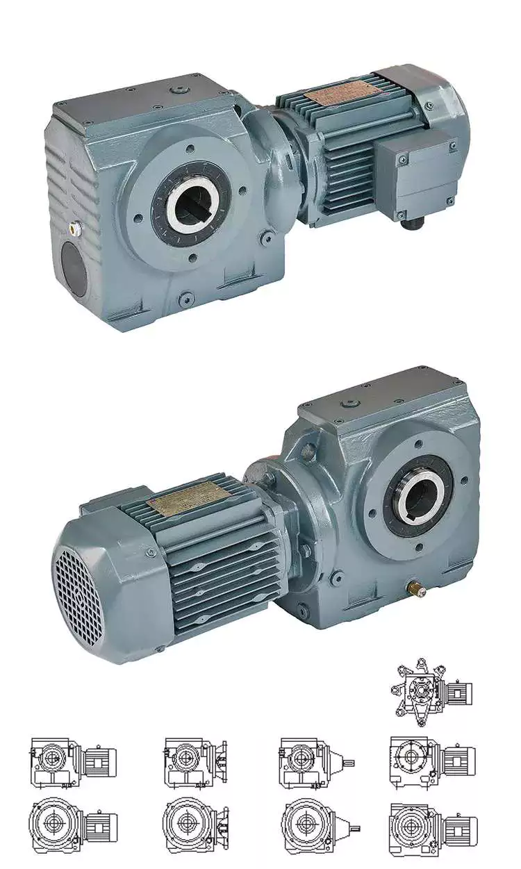
China 24V Turbo Reduction Gearbox Gear Motor Worm Gear Motor Speed Gearbox Reducer worm gearbox angle

Error:获取返回内容失败,
Your session has expired. Please reauthenticate.
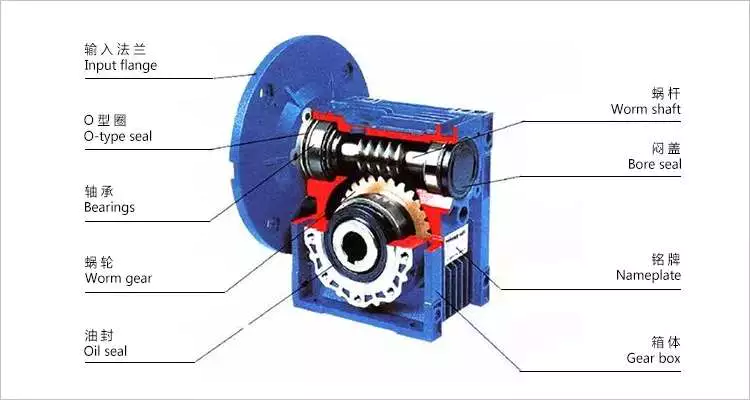
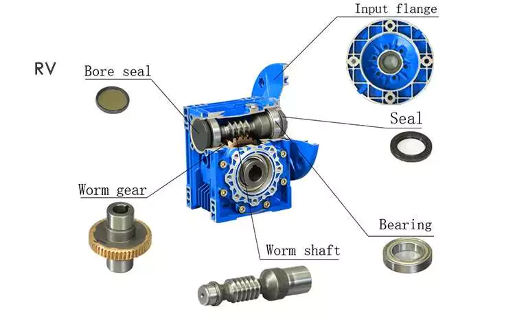
worm reducer

Worm reducer gearbox

Worm reducer gearboxes are commonly used to reduce the Agknx produced by a rotating shaft. They can achieve reduction ratios of five to sixty. In contrast, a single-stage hypoid gear can achieve up to a 120:1 reduction ratio. For further reduction, another type of gearing is used. So, a single stage worm reducer gearbox cannot achieve higher ratios than these.

Mechanics

A worm reducer gearbox is an auxiliary mechanical device that uses worms to reduce the size of a rotating shaft. These worms have a range of tooth forms. One form is a line weave twist surface. Another is a trapezoid based on a central cross section. The trapezoid can be perpendicular to the tooth cross section, or it can be normal to the root cross section. Other forms include involute helicoids and convolute worms, which use a straight line intersecting the involute generating line.
Worm gears are lubricated with a special lubricant. Because worm gears are complex, it’s important to use the correct lubricant. Worm gear manufacturers provide approved lubricants for their gears. Using unapproved gear oil can damage your reducer gearbox’s efficiency. The right lubricant depends on several factors, including load, speed, duty cycle, and expected operating temperatures.
The efficiency of a worm gear reducer gearbox depends on several factors, including losses at gear mesh, losses in the bearings, and windage in the oil seal lip. In addition, the worm gear reducer gearbox’s efficiency varies with ambient temperature and operating temperature. The worm gear reducer gearbox’s efficiency can also vary with the ratio of the load. Moreover, worm gear reducer gearboxes are subject to break-in.
Worm gear reducer gearboxes are used in many different applications. They are typically used in small electric motors, but they’re also used in conveyor systems, presses, elevators, and mining applications. Worm gears are also commonly found in stringed musical instruments.
Worm gears have excellent reduction ratios and high Agknx multiplication, and they’re often used as speed reducer gearboxes in low to medium-speed applications. However, the efficiency of worm gear reducer gearboxes decreases with increasing ratios.

Sizes

Worm reducer gearboxes come in different sizes and tooth shapes. While the tooth shape of one worm is similar to the other, different worms are designed to carry a different amount of load. For example, a circular arc worm may have a different tooth shape than one with a secondary curve. Worm gears can also be adjusted for backlash. The backlash is the difference between the advancing and receding arc.
There are two sizes of worm reducer gearboxes available from Agknx Transmission. The SW-1 and SW-5 models offer ratios of 3.5:1 to 60:1 and 5:1 to 100:1 respectively. The size of the worm reducer gearbox is determined by the required gear ratio.
Worm gears have different thread counts. One is based on the central cross-section of the worm, and the other is on the right. Worm gears can have either a single or double thread. Single-threaded gears will reduce speed by 50 percent, while double-threaded gears will reduce speed by 25 percent.
Worm gear reducer gearboxes are lightweight and highly reliable. They can accommodate a variety of NEMA input flanges and hollow output bore sizes. Worm reducer gearboxes can be found at 6 regional warehouses, with prepaid freight. To make a purchasing decision, you should consider the horsepower and Agknx requirements of your specific application.
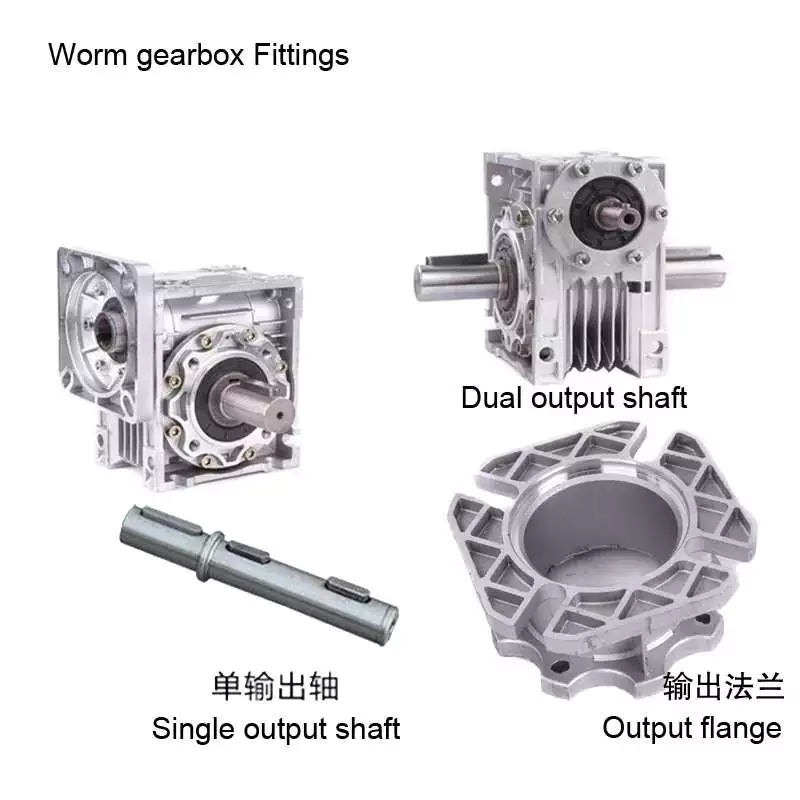
worm reducer

Applications

The Worm reducer gearbox market is a global business that is dominated by the North American and European regions. The report provides in-depth information on the market trends, key challenges, and opportunities. It also examines the current state of the industry and projects future market growth. The report is organized into segments based on product type, major geographical regions, and application. It also presents statistics and key data about the market.
Worm gear reducer gearboxes have many applications. They can be used to increase the speed of convey belts. They also help reduce noise. Worm gears have many teeth that touch the gear mesh, which makes them quieter. Moreover, the worm gears require only a single stage reducer gearbox, reducing the number of moving parts in the system.
The worm gear has long life and is suitable for different industries. It is a perfect choice for elevators and other applications that need fast stopping and braking. Its compact size and ability to hold a load make it suitable for these applications. It also prevents the load from free-falling as a result of a sudden braking. Worm gears can also be used in heavy-duty machinery such as rock crushers.
Worm gears are similar to ordinary gears except that they transfer motion at a 90-degree angle. As a result, the worm gears are extremely quiet, making them a suitable option for noise sensitive applications. They are also excellent for low-voltage applications, where the noise is critical.
Worm gears are ideal for applications with space restrictions, because they require fewer gear sets. The worm gears also allow for a smaller gearbox size. Consequently, they are the perfect choice for machines that are space-constrained, such as conveyors and packaging equipment.

Cost

The lifespan of a worm gear reducer gearbox is comparable to other gear reducer gearboxes. Worm gears have a long history of innovation and use in various industries, from shipbuilding to automobile manufacturing. Today, these gear reducer gearboxes are still popular with engineers. However, there are some things to keep in mind before buying one.
In the first place, a worm reducer gearbox needs to be affordable. Generally, a worm reducer gearbox costs about $120. The price varies with the brand name and features. Some products are more expensive than others, so be sure to shop around for the best price. In addition, it is important to consider the quality and design of the worm reducer gearbox before making a purchase.
Worm gear manufacturers have made significant advancements in materials, design and manufacturing. These advancements, along with the use of advanced lubricants, have resulted in significant increases in efficiency. For example, double enveloping worm gear reducer gearboxes have improved efficiency by three to eight percentage points. This improvement was achieved through rigorous testing of manufacturing processes and materials. With these improvements, worm gear reducer gearboxes have become more desirable in today’s market.
Worm reducer gearboxes are extremely versatile and reliable, and are available in a variety of sizes. Domestic manufacturers usually stock a large selection of reducer gearboxes, and are often able to ship them the same day you place your order. Most major domestic worm gear reducer gearbox manufacturers also share some critical mounting dimensions, such as the output shaft diameter, the mounting hole location, and the overall reducer gearbox housing height. Most manufacturers also offer standardized gear ratios. Some manufacturers have also improved gear design and added synthetic lubricants for better performance.
In addition, different tooth shapes of worms can increase their load carrying capacity. They can be used on secondary curves and circular arc cross sections. Moreover, the pitch point defines the boundary of the cross section. The mesh on the receding arc is smoother than that of the advancing arc. However, in the case of negative shifting, most of the mesh is on the receding arc.
worm reducer

Self-locking function

A worm reducer gearbox has a self-locking function. When a worm is fitted with all of its addendum teeth, the total number of teeth in the system should be greater than 40. This self-locking function is achieved through the worm’s rack and pinion mechanism. The worm’s self-locking feature can prevent the load from being dropped and is useful for many applications.
The self-locking function of a worm reducer gearbox is possible for two main reasons. First of all, a worm reducer gearbox uses two or more gears. One gear is placed at the input, and the other gear runs the output shaft. This mechanism produces a torque, which is transmitted to a spur gear.
Worm reducer gearboxes can be used in a variety of industrial applications. Because of their self-locking function, they are useful for preventing back-driving. They are also helpful for lifting and holding loads. Their self-locking mechanism allows for a large gear reduction ratio without increasing the size of a gear box.
Self-locking gears can be used to prevent back-driving and inertial driving. This is useful for many industries and can prevent backdriving. However, one major disadvantage of self-locking gears is their sensitivity to operating conditions. Lubrication, vibration, and misalignment can affect their reliability.
Embodiments of the invention provide a self-locking mechanism that prevents back-driving but allows forward-driving. The self-locking mechanism may comprise first and second ratchet cams disposed about a gear member. A releasable coupling member may be interposed between the gear member and the ratchet cam. This facilitates selective coupling and decoupling.
The worm reducer gearbox has several advantages. Its compact design is ideal for many mechanical transmission systems. It also provides greater load capacity than a cross-axis helical gear mechanism.

China 24V Turbo Reduction Gearbox Gear Motor Worm Gear Motor Speed Gearbox Reducer     worm gearbox angleChina 24V Turbo Reduction Gearbox Gear Motor Worm Gear Motor Speed Gearbox Reducer     worm gearbox angle
editor by Cx 2023-07-03

China Hot selling G3 Inline Shaft Mounted Speed Reduction Gear Reducer Motor Gearbox with Hot selling

Product Description


Product Description

MAIN FEATURES:
1) Made of high quality material,  non-rusting;Both flange and foot mounting available and suitable for all-round installation
2) Large output torque and high radiating efficiency
3)Precise grinding helical gear with Smooth running and low noise, no deformation,can work long time in dreadful condition
4)Nice appearance, durable service life and small volume, compact structure
5)Both 2 and 3 stage available with wide ratio range from 5 to 200
6)Different output shaft diameter available -40-50mm
7)Modular construction enlarge ratio from 5 to 1400

MAIN MATERIALS:
1)housing with aluminium alloyand cast iron material;
2)Output Shaft Material:20CrMnTi
3)Good quality no noise bearings to keep long service life
4)High performance oil seal to prevent from oil leakage

APPLICATIONS:
G3 Series helical gear motor are wide used for all kinds of automatic equipment, such as chip removal machine, conveyor, packaging equipment, woodworking machinery, farming equipment, slurry scraper ,dryer, mixer and so on.

Detailed Photos

Product Parameters


(n1=1400r/min  50hz)
norminal ratio 5 10 15 20 25 30 40 50 60 80 100 100 120 160   200   
0.1kw output shaft  Ø18 Ø22
n2* (r/min) 282 138 92 70 56 46 35 28 23 18 14 11 9 7
M2(Nm) 50hz 3.2 6.5 9.8 12.9 16.1 19.6 25.7 31.1 37.5 49.5 62.9 76.1 100.7 125.4
60hz 3 5 8 11 13 17 21 26 31 41 52 63 84 105
Fr1(N) 588 882 980 1180 1270 1370 1470 1570 2160 2450 2450 2450 2450 2450 2450
Fr2(N) 176
norminal ratio 5 10 15 20 25 30 40 50 60 80 100 100 120 160 200
0.2kw output shaft  Ø18 Ø22 Ø28
n2* (r/min) 282 138 92 70 56 45 35 29 23 18 14 13 12 8 7
M2(Nm) 50hz 6.5 12.6 19.1 26.3 32.6 38.9 50.4 63 75.6 100.8 103.9 125.4 150 200.4 250.7
60hz 5.4 10.5 16.6 21.9 27.1 32.4 42 52.5 63 84 86.6 104.5 125 167 208.9
Fr1(N) 588 882 980 1180 1270 1760 1860 1960 2160 2450 2450 2840 3330 3430 3430
Fr2(N) 196
norminal ratio 5 10 15 20 25 30 40 50 60 80 100 100 120 160 200
0.4kw output shaft  Ø22 Ø28 Ø32
n2* (r/min) 288 144 92 72 58 47 36 29 24 18 14 14 12 9 7
M2(Nm) 50hz 12.9 25 38.6 51.4 65.4 78.2 100.7 125.4 150 200.4 206.8 250.7 301.1 400.7 461.8
60hz 10.7 20.8 32.1 42.9 54.5 65.2 83.9 104.5 125 167 172.3 208.9 250.9 333.9 384.8
Fr1(N) 882 1180 1370 1470 1670 2550 2840 3140 3430 3430 3430 4900 5880 5880 5880
Fr2(N) 245
norminal ratio 5 10 15 20 25 30 40 50 60 80 100 100 120 160 200
0.75kw output shaft  Ø28 Ø32 Ø40
n2* (r/min) 278 140 94 69 58 46 35 29 24 18 14 14 11 9 7
M2(Nm) 50hz 24.6 48.2 72.9 97.5 122.1 145.7 187.5 235.7 282.9 376.1 387.9 439 527 703 764
60hz 20.5 40.2 60.7 81.3 201.8 121.4 156.3 196.4 235.7 313.4 323.2 366 439 585 732
Fr1(N) 1270 1760 2160 2350 2450 4571 4210 4610 5490 5880 5880 7060 7060 7060 7060
Fr2(N) 294
norminal ratio 5 10 15 20 25 30 40 50 60 80 100 100 120 160 200
1.5kw output shaft  Ø32 Ø40 Ø50
n2* (r/min) 280 140 93 70 55 47 34 27 24 17 14 13 12 8 7
M2(Nm) 50hz 48.2 97.5 145.7 193.9 242.1 272 351 439 527 703 724 878 1060 1230 1230
60hz 40.2 81.3 121.4 161.6 201.8 226 293 366 439 585 603 732 878 1170 1230
Fr1(N) 1760 2450 2840 3230 3820 5100 5880 7060 7060 7060 7060 9800 9800 9800 9800
Fr2(N) 343
norminal ratio 5 10 15 20 25 30 40 50 60 80 100        
2.2kw output shaft  Ø40 Ø50  
n2* (r/min) 272 136 95 68 54 45 36 28 24 18 14        
M2(Nm) 50hz 67 133 200 266 332 399 515 644 773 1571 1230        
60hz 56 111 167 221 277 332 429 537 644 858 1080        
Fr1(N) 2160 3140 3530 4571 4700 6960 7250 8620 9800 9800 9800        
Fr2(N) 392

Outline and mounting dimension:

G3FM: THREE PHASE GEAR MOTOR WITH FLANGE                                                                                       (n1=1400r/min)
Power kw output shaft ratio A F I J M O O1 P Q R S T U W X Y Y1
standard brake
0.1kw  Ø18 5–30-40-50 236 270 192.5 11 16.5 170 4 10 30 145 35 18 20.5 129 6 157 80 81
 Ø22 -160-200 262 296 197.5 11 19 185 4 12 40 148 47 22 24.5 129 6 171.5 89.5 83.5
0.2kw  Ø18 5- 267 270 192.5 11 16.5 170 4 10 30 145 35 18 20.5 129 6 161 80 81
 Ø22 -80-100 293 296 197.5 11 19 185 4 12 40 148 47 22 24.5 129 6 171.5 89.5 83.5
 Ø28 306 309.5 208.5 11 23.5 215 4 15 45 170 50 28 31 129 8 198.5 105.5 88
0.4kw  Ø22 5- 314 324.5 204 11 19 185 4 12 40 148 47 22 24.5 139 6 171.5 89.5 88.5
 Ø28 -80-100 330 337.5 215 11 23.5 215 4 15 45 170 50 28 31 139 8 198.5 105.5 93
 Ø32 349 357 229.5 13 28.5 250 4 15 55 180 60 32 35 139 10 234 126 98
0.75kw  Ø28 5- 350.5 343.5 227.5 11 23.5 215 4 15 45 170 50 28 31 159 8 198.5 105.5 103
 Ø32 -80-100 379.5 387 242 13 28.5 250 4 15 55 180 60 32 35 159 10 234 126 108
 Ø40 401.5 408.5 270 18 34 310 5 18 65 230 71 40 43 185 12 284 149 126.5
1.5kw  Ø32 5- 420.5 441 254 13 28.5 250 5 15 55 180 60 32 35 185 10 234 126 121
 Ø40 -80-100 457.5 478 270 18 34 310 5 18 65 230 71 40 43 185 12 284 149 126.5
 Ø50 485.5 506 300 22 40 360 5 25 75 270 83 50 53.5 185 14 325 173.5 132.5
2.2kw  Ø40 5- 466.5 487 270 18 34 310 5 18 65 230 71 40 43 185 12 284 149 126.5
 Ø50 -80-100 510.5 531 300 22 40 360 5 25 75 270 83 50 53.5 185 14 325 173.5 132.5


G3LM: THREE PHASE GEAR MOTOR WITH FOOT                                                                                                               (n1=1400r/min)
Power kw output shaft ratio A D E F J G H K P S T   U  V W   X  Y   Y1       
standard brake
0.1kw  Ø18 5–30-40-50 236 270 40 110 135 16.5 65 9 45 30 18 20.5 129 183 6 133 85 10
 Ø22 -160-200 262 296 65 130 155 19 90 11 55 40 22 24.5 129 193 6 139.5 90 12
0.2kw  Ø18 5- 267 270 40 110 135 16.5 65 9 45 30 18 20.5 129 183 6 133 85 10
 Ø22 -80-100 293 296 65 130 155 19 90 11 55 40 22 24.5 129 193 6 139.5 90 12
 Ø28 306 309.5 90 140 175 23.5 125 11 65 45 28 31 129 203 8 170 110 15
0.4kw  Ø22 5- 314 324.5 65 130 155 19 90 11 55 40 22 24.5 139 199.5 6 141.5 90 12
 Ø28 -80-100 330 337.5 90 140 175 23.5 125 11 65 45 28 31 139 210 8 170 110 15
 Ø32 349 357 130 170 208 28.5 170 13 70 55 32 35 139 226 10 198 130 18
0.75kw  Ø28 5- 350.5 343.5 90 140 175 23.5 125 11 65 45 28 31 159 222 8 170 110 15
 Ø32 -80-100 379.5 387 130 170 208 28.5 170 13 70 55 32 35 159 238.5 10 198 130 18
 Ø40 401.5 408.5 150 210 254 34 196 15 90 65 40 43 185 249 12 230 150 20
1.5kw  Ø32 5- 420.5 441 130 170 208 28.5 170 13 70 55 32 35 185 250.5 10 198 130 18
 Ø40 -80-100 457.5 478 150 210 254 34 196 15 90 65 40 43 185 260 12 230 150 20
 Ø50 485.5 506 160 230 290 40 210 18 100 75 50 53.5 185 288 14 265 170 25
2.2kw  Ø40 5- 466.5 487 150 210 254 34 196 15 90 65 40 43 185 260 12 230 150 20
 Ø50 -80-100 510.5 531 160 230 290 40 210 18 100 75 50 53.5 185 288 14 265 170 25


G3FS: IEC GEAR REDUCER WITH FOOT                                                                                                                           (n1=1400r/min)
Power kw output shaft ratio A B C F I J L M N O O1 P Q R S S1 T T1 W W1 X Y Y1
0.12kw  Ø18 5–30-40-50 147 95 115 154 11 16.5 4.5 170 140 4 10 30 145 35 18 11 20.5 12.8 6 4 163 80 86.5
 Ø22 -160-200 173 95 115 164 11 19 4.5 185 140 4 12 40 148 47 22 11 24.5 12.8 6 4 171.5 89.5 89
0.18kw  Ø18 5- 147 95 115 154 11 16.5 4.5 170 140 4 10 30 145 35 18 11 20.5 12.8 6 4 163 80 86.5
 Ø22 -80-100 173 95 115 164 11 19 4.5 185 140 4 12 40 148 47 22 11 24.5 12.8 6 4 171.5 89.5 89
 Ø28 186.5 95 115 186 11 23.5 4.5 215 140 4 15 45 170 50 28 11 31 12.8 8 4 198.5 105.5 93.5
0.37kw  Ø22 5- 181.5 110 130 164 11 19 4.5 185 160 4 12 40 148 47 22 14 24.5 16.3 6 5 201 89.5 99
 Ø28 -80-100 198 110 130 186 11 23.5 4.5 215 160 4 15 45 170 50 28 14 31 16.3 8 5 198.5 105.5 103.5
 Ø32 216.5 110 130 215 13 28.5 4.5 250 160 4 15 55 180 60 32 14 35 16.3 10 5 234 126 108.5
0.75kw  Ø28 5- 206.5 130 165 185 11 23.5 4.5 215 200 4 15 45 170 50 28 19 31 21.8 8 6 216.5 105.5 123.5
 Ø32 -80-100 235 130 165 215 13 28.5 4.5 250 200 4 15 55 180 60 32 19 35 21.8 10 6 236.5 126 128.5
 Ø40 260.5 130 165 270 18 34 4.5 310 200 5 18 65 230 71 40 19 43 21.8 12 8 284 149 134
1.5kw  Ø32 5- 252 130 165 215 13 28.5 4.5 250 200 5 15 55 180 60 32 24 35 27.3 10 8 236.5 126 128.5
 Ø40 -80-100 293.5 130 165 270 18 34 4.5 310 200 5 18 65 230 71 40 24 43 27.3 12 8 284 149 134
 Ø50 321.5 130 165 300 22 40 4.5 360 200 5 25 75 270 83 50 24 53.5 27.3 14 8 323.5 173.5 140
2.2kw  Ø40 5- 290 180 215 270 18 34 5.5 310 250 5 18 65 230 71 40 28 43 31.3 12 8 284 149 134
 Ø50 -80-100 334 180 215 300 22 40 5.5 360 250 5 25 75 270 83 50 28 53.5 31.3 14 8 323.5 173.5 140


G3LS: IEC GEAR REDUCER WITH FOOT                                                                                                                           (n1=1400r/min)  
Power kw output shaft ratio A B C D E F G H J K L N P S S1 T T1 W W1 X Y Y1 Z
0.12kw  Ø18 5–30-40-50 147 95 115 40 110 135 65 9 16.5 45 4.5 140 30 18 11 20.5 12.8 6 4 138.5 85 10 M8
 Ø22 -160-200 173 95 115 65 130 154 90 11 19 55 4.5 140 40 22 11 24.5 12.8 6 4 141 90 12 M8
0.18kw  Ø18 5- 147 95 115 40 110 135 65 9 16.5 45 4.5 140 30 18 11 20.5 12.8 6 4 138.5 85 10 M8
 Ø22 -80-100 173 95 115 65 130 154 90 11 19 55 4.5 140 40 22 11 24.5 12.8 6 4 141 90 12 M8
 Ø28 186.5 95 115 90 140 175 125 11 23.5 65 4.5 140 45 28 11 31 12.8 8 4 170 110 15 M8
0.37kw  Ø22 5- 181.5 110 130 65 130 154 90 11 19 55 4.5 160 40 22 14 24.5 16.3 6 5 151 90 12 M8
 Ø28 -80-100 198 110 130 90 140 175 125 11 23.5 65 4.5 160 45 28 14 31 16.3 8 5 170 110 15 M8
 Ø32 216.5 110 130 130 170 208 170 13 28.5 70 4.5 160 55 32 14 35 16.3 10 5 198 130 18 M8
0.75kw  Ø28 5- 206.5 130 165 90 140 175 125 11 23.5 65 4.5 200 45 28 19 31 21.8 8 6 186.5 110 15 M10
 Ø32 -80-100 235 130 165 130 170 208 170 13 28.5 70 4.5 200 55 32 19 35 21.8 10 6 201.5 130 18 M10
 Ø40 260.5 130 165 150 210 254 196 15 34 90 4.5 200 65 40 19 43 21.8 12 8 230 150 20 M10
1.5kw  Ø32 5- 252 130 165 130 170 208 170 13 28.5 70 4.5 200 55 32 24 35 27.3 10 8 201.5 130 18 M10
 Ø40 -80-100 293.5 130 165 150 210 254 196 15 34 90 4.5 200 65 40 24 43 27.3 12 8 230 150 20 M10
 Ø50 321.5 130 165 160 230 290 210 18 40 100 4.5 200 75 50 24 53.5 27.3 14 8 265 170 25 M10
2.2kw  Ø40 5- 290 180 215 150 210 254 196 15 34 90 5.5 250 65 40 28 43 31.3 12 8 230 150 20 M12
 Ø50 -80-100 334 180 215 160 230 290 210 18 40 100 5.5 250 75 50 28 53.5 31.3 14 8 265 170 25 M12

Company Profile

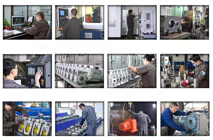
We are a professional reducer manufacturer located in HangZhou, ZHangZhoug province.Our leading products is  full range of RV571-150 worm reducers , also supplied GKM hypoid helical gearbox, GRC inline helical gearbox, PC units, UDL Variators and AC Motors, G3 helical gear motor.Products are widely used for applications such as: foodstuffs, ceramics, packing, chemicals, pharmacy, plastics, paper-making, construction machinery, metallurgic mine, environmental protection engineering, and all kinds of automatic lines, and assembly lines.With fast delivery, superior after-sales service, advanced producing facility, our products sell well  both at home and abroad. We have exported our reducers to Southeast Asia, Eastern Europe and the Middle East and so on.Our aim is to develop and innovate on the basis of high quality, and create a good reputation for reducers.

Workshop:


Exhibition

ZheJiang PTC Fair:

Packaging & Shipping

After Sales Service

1.Maintenance Time and Warranty:Within 1 year after receiving goods.
2.Other ServiceIncluding modeling selection guide, installation guide, and problem resolution guide, etc

FAQ

1.Q:Can you make as per customer drawing?
A: Yes, we offer customized service for customers accordingly. We can use customer’s nameplate for gearboxes.
2.Q:What is your terms of payment ?
A: 30% deposit before production,balance T/T before delivery.
3.Q:Are you a trading company or manufacturer?
A:We are a manufacurer with advanced equipment and experienced workers.
4.Q:What’s your production capacity?
A:4000-5000 PCS/MONTH
5.Q:Free sample is available or not?
A:Yes, we can supply free sample if customer agree to pay for the courier cost
6.Q:Do you have any certificate?
A:Yes, we have CE certificate and SGS certificate report.

Contact information:
Ms Lingel Pan
For any questions just feel free ton contact me. Many thanks for your kind attention to our company!

Application: Motor, Machinery, Marine, Agricultural Machinery, Power Transmission Applications
Function: Distribution Power, Clutch, Change Drive Torque, Change Drive Direction, Speed Changing, Speed Reduction
Layout: Coaxial
Hardness: Hardened Tooth Surface
Installation: Vertical or Horizontal Type
Step: Two Stage- Three Stage
Samples:
US$ 35/Piece
1 Piece(Min.Order)

|
Request Sample

Customization:
Available

|

worm reducer

What is a worm gear reducer gearbox?

The worm gear reducer gearbox is used to change the output speed of the mechanical device. It consists of worm and helical gears mounted on the input side of the equipment. In some cases, this gear reduction system can be multi-stage, enabling extremely low output speeds. It has the advantages of low energy consumption and low vibration.
Hollow shaft worm gear reducer gearbox

Worm gear reducer gearbox is an effective device to reduce the speed of mechanical equipment. The use of hard steel or non-ferrous metals for the worm increases its efficiency. Worms made of hard steel generate more heat than worms made of mild steel. Different thermal expansion results in gaps between mating surfaces. Despite its many benefits, worm gear reducer gearboxes are prone to oil leakage, which can be a problem for a number of reasons.
Hollow shaft worm gear reducer gearboxes are available in different gear ratios and are compatible with many motor types. Some are available in dual-axis and single-axis configurations and can be mounted horizontally or vertically. They are also available in intermediate ratios, as well as four- and five-speed transmission types. They can also be connected with additional output shafts.
Another type of worm gear reducer gearbox is the multi-stage variety. This gear reducer gearbox has multiple stages, enabling it to reduce speed with extremely low output speeds. In addition to the large transmission ratio, the multi-stage gear reducer gearbox has low noise, low vibration and low energy consumption.
Worm gear reducer gearboxes offer space-saving solutions as well as increased torque. Agknx Gearbox offers worm gear reducer gearboxes that solve common deceleration problems. The company has also expanded its product range into the bathroom market. Compared with the standard gearbox, the worm gear reducer gearbox has the characteristics of lower price and better torque output.
Agknx worm gear

The Agknx type worm gear reducer gearbox has multi-tooth line contact and is widely used in heavy machinery. These gears are characterized by a high load-carrying capacity, but they are highly sensitive to misalignment and manufacturing errors. However, by employing point contact, these gears can be made more reliable and can withstand higher loads.
Another major advantage of the Agknx worm gear is its high load capacity. The tooth profile design of the gears has a high relative slip ratio, which improves efficiency and load capacity. In addition, the large angle between the sliding direction and the contact line provides a low coefficient of friction. The Agknx worm gear also features premium carburized steel and phosphor bronze castings for exceptional durability. In addition, the tooth profile is very precise, the operation is quiet, and the speed fluctuation is small.
Agknx worm gear reducer gearboxes are designed to operate for up to ten hours per day with an even load. The design of this worm gear reducer gearbox stems from Sumitomo Heavy Industries’ extensive experience in gear reducer gearboxes. The smooth surface texture and precise tooth profile of the gears ensure that the gears can withstand high loads without damaging the lubricant film. In addition, Agknx worm shafts are specially designed to have the right stiffness.
Agknx worm gear reducer gearboxes are designed to maximize load capacity while minimizing energy consumption. Its fully meshed teeth reduce surface pressure on the worm gear teeth and increase load capacity.
worm reducerDouble throat worm gear

There are a few things to consider when choosing a dual-throat worm gear. First, the diameter of the root circle must match the circle pitch of the larger gear. This measurement is usually done by measuring the distance between adjacent teeth. Alternatively, the worm’s normal module can be used. It is the value entered in the worm module dialog. In addition, the axial pitch of the worm should be equal to the pitch diameter of the circular pitch.
Double-throat worm gears are an excellent choice for heavy and heavy-duty applications. The design of this worm gear is ideal for heavy-duty applications as it provides a tighter connection between the worm and the gear. It is also more compact than other types of gear and is comparable to a fine-pitch lead screw.
The efficiency of a double-throat worm gear depends on the material of the gear and worm. Typically, gears are made of case-hardened steel, while worm gears are made of bronze or cast iron. In some cases, a combination of cast iron and bronze can be used.
The deflection of the worm shaft is also affected by the tooth parameters. Tooth height, pressure angle, and size factors all affect the deflection of the worm shaft. In addition, the number of worm threads is another important parameter that affects the deflection of the worm shaft.
Double-throat worm gears are commonly used in industrial applications where high drive reduction is required. The worm has a concave and internal tooth structure that can be adjusted to achieve various ratios. Worm gears and worm gear assemblies must be properly mounted on their shafts to prevent back drive.
Brass worm gear

The basic working principle of the brass worm gear reducer gearbox is the same as that of the traditional worm gear reducer gearbox. Its axial pitch must be equal to the circumferential pitch of the larger gear. The single-thread design advances one tooth per revolution, while the double-thread design advances two teeth. The threads on the worm are either left-handed or right-handed. The lead of a worm is the distance a point on the thread of the worm moves in one revolution. The lead angle is the angle tangent to the pitch of the cylinder and the axis of the worm.
Double-thread worm gear reducer gearboxes are best for heavy loads. It provides the tightest connection between the worm and the gear. Assembly of the worm gear requires precise mounting. The keyway installation method involves drilling a square cut in the gear hole. This prevents the worm from rotating on the shaft and helps transmit torque. Then use the set screw to secure the gear to the hub.
The large fuel tank helps keep the worm gear clean and reduces heat. It also provides lubrication for extended life. Worm gear reducer gearboxes with oil reservoirs provide a lubricated environment and low-friction surfaces. Additionally, it offers multi-position installation flexibility. Additionally, its housing is cross-milled for precise alignment. It also features internal baffles for leak-free ventilation.
I260 series worm gear reducer gearboxes are one-piece iron casings with solid or hollow output shafts and tapered roller bearings. This gear reducer gearbox is designed for low to medium-horsepower applications. This gear reducer gearbox is a cost-effective option with low initial cost, the high gear ratio, and high torque in a compact package. Also, it is more shock resistant than other gear reducer gearboxes.
worm reducerBrass worm gear

Brass worm gear reducer gearbox is a reduction gear. This type of gear can provide a lot of reduction in a small package. This type of gear reducer gearbox also has the ability to generate high torque. However, it is important to understand that this gear reducer gearbox has thermal limitations, which reduce its efficiency. The choice of lubricant for this gear reducer gearbox is very flexible. However, being a yellow metal, it is important to remember that the lubricant must be non-reactive.
Worm gears are used in many consumer and industrial applications and have high reduction ratios. These gears are produced in various configurations and sizes. Worm gears are similar to spur gears but have non-parallel shafts. Worm gears are also suitable for applications requiring low output speed but high torque.
Worm gears have some distinct advantages over other gears. First, unlike standard gears, the worm rotates in a worm-like motion. This mechanism prevents reverse movement. This is because the lead angle of the worm gear is small. Additionally, the worms self-lock, helping to prevent reversal. However, this mechanism is not entirely reliable. Worm gears can be found in elevators, fishing reels, sprockets, and automotive power steering.
Another advantage of worm gears is that they are easy to manufacture. The rationale behind this design is to have two mutually perpendicular axes. Then, two or more threads are added to the worm gear. The common tangent between these two shafts intersects the pitch line of the worm gear shaft. This is the basis of transfer speed.

China Hot selling G3 Inline Shaft Mounted Speed Reduction Gear Reducer Motor Gearbox   with Hot selling		China Hot selling G3 Inline Shaft Mounted Speed Reduction Gear Reducer Motor Gearbox   with Hot selling
editor by CX 2023-06-07

China Blue Worm Gear Transmission Speed Reduction Gear Box with Motor double worm gearbox

Item Description


Solution Description

Major Supplies:
1)housing:aluminium alloy ADC12(dimensions 571-090) die cast iron HT200(size 110-150)
two)Worm:20Cr, ZI Involute profile carbonize&quencher heat remedy make equipment surface hardness up to 56-sixty two HRC Following precision grinding, carburization layer’s thickness among .3-.5mm.
three)Worm Wheel:wearable stannum alloy CuSn10-1

Thorough Photographs

Mix Alternatives:
Enter:with enter shaft, With square flange,With IEC regular input flange
Output:with torque arm, output flange, single output shaft, double output shaft, plastic include
Worm reducers are obtainable with diffferent mixtures: NMRV+NMRV, NMRV+NRV, NMRV+Laptop, NMRV+UDL, NMRV+MOTORS

Exploded Check out:

Merchandise Parameters

 
Outdated Model     
  New Model     Ratio     Center Distance  Electricity Enter Dia.  Output Dia.    Output Torque Fat
RV571     7.5~100   25mm   .06KW~.12KW  Φ9 Φ11 21N.m  .7kgs
RV030 RW030 seven.5~one hundred 30mm   .06KW~.25KW Φ9(Φ11) Φ14 45N.m  one.2kgs
RV040 RW040 seven.5~one hundred 40mm   .09KW~.55KW Φ9(Φ11,Φ14) Φ18(Φ19) 84N.m  2.3kgs
RV050 RW050 seven.5~one hundred 50mm   .12KW~1.5KW Φ11(Φ14,Φ19) Φ25(Φ24) 160N.m  3.5kgs
RV063 RW063 seven.5~a hundred 63mm   .18KW~2.2KW Φ14(Φ19,Φ24) Φ25(Φ28) 230N.m  six.2kgs
RV075 RW075 seven.5~a hundred 75mm   .25KW~4.0KW Φ14(Φ19,Φ24,Φ28)  Φ28(Φ35) 410N.m  9.0kgs
RV090 RW090 7.5~one hundred 90mm   .37KW~4.0KW Φ19(Φ24,Φ28) Φ35(Φ38) 725N.m  13.0kgs
RV110 RW110 seven.5~100 110mm   .55KW~7.5KW Φ19(Φ24,Φ28,Φ38)   Φ42 1050N.m  35.0kgs
RV130 RW130 7.5~one hundred 130mm   .75KW~7.5KW Φ24(Φ28,Φ38) Φ45 1550N.m  forty eight.0kgs
RV150 RW150 7.5~100 150mm     2.2KW~15KW Φ28(Φ38,Φ42) Φ50   eighty four.0kgs

GMRV Define Dimension:

GMRV A B C C1 D(H8) E(h8) F G G1 H H1 I M N O P Q R S T BL β b t V  
030 80 97 54 forty four fourteen fifty five 32 fifty six 63 65 29 fifty five forty fifty seven thirty 75 forty four six.5 21 five.5 M6*ten(n=4) 5 16.three 27
040 a hundred 121.5 70 sixty 18(19) 60 forty three seventy one seventy eight 75 36.five 70 fifty 71.five 40 87 fifty five six.5 26 six.5 M6*ten(n=4) 45° 6 20.8(21.8) 35
050 120 one hundred forty four eighty 70 twenty five(24) 70 forty nine 85 92 eighty five forty three.five 80 sixty 84 50 one hundred 64 eight.5 thirty seven M8*12(n=4) 45° 8 28.3(27.3) 40
063 144 174 a hundred eighty five 25(28) eighty 67 103 112 95 fifty three ninety five 72 102 63 a hundred and ten 80 eight.five 36 8 M8*12(n=8) 45° eight 28.3(31.3) fifty
075 172 205 a hundred and twenty ninety 28(35) ninety five 72 112 a hundred and twenty one hundred fifteen 57 112.five 86 119 75 a hundred and forty 93 eleven forty ten M8*14(n=8) 45° 8(10) 31.3(38.3) 60
090 206 238 one hundred forty a hundred 35(38) a hundred and ten 74 a hundred thirty 140 130 sixty seven 129.5 103 135 ninety 160 102 13 45 eleven M10*sixteen(n=8) 45° ten 38.3(forty one.3) 70
110 255 295 one hundred seventy 115 42 130 a hundred and forty four 155 a hundred sixty five seventy four 160 127.five 167.5 110 200 125 fourteen fifty fourteen M10*eighteen(n=8) 45° 12 forty five.3 eighty five
130 293 335 200 a hundred and twenty 45 a hundred and eighty 155 one hundred seventy 215 eighty one 179 146.five 187.5 130 250 a hundred and forty sixteen 60 15 M12*20(n=8) 45° 14 forty eight.eight a hundred
a hundred and fifty 340 400 240 a hundred forty five 50 a hundred and eighty 185 200 215 96 210 a hundred and seventy 230 one hundred fifty 250 one hundred eighty 18 72.5 eighteen M12*22(n=8) 45° 14 53.8  120  

Organization Profile

About CZPT Transmission:
We are a professional reducer company situated in HangZhou, ZHangZhoug province.
Our top items is  full selection of RV571-150 worm reducers , also supplied GKM hypoid helical gearbox, GRC inline helical gearbox, Pc models, UDL Variators and AC Motors, G3 helical gear motor.
Merchandise are widely used for apps these kinds of as: foodstuffs, ceramics, packing, chemical substances, pharmacy, plastics, paper-producing, development machinery, metallurgic mine, environmental security engineering, and all types of automated lines, and assembly traces.
With fast shipping and delivery, excellent right after-revenue support, advanced creating facility, our merchandise market well  both at home and overseas. We have exported our reducers to Southeast Asia, Jap Europe and Center East and so on.Our purpose is to build and innovate on basis of higher top quality, and produce a good reputation for reducers.

 Packing details:Plastic Bags+Cartons+Wooden Situations , or on ask for
We participate Germany Hannver Exhibition-ZheJiang PTC Fair-Turkey Earn Eurasia 

Logistics

After Sales Service

1.Servicing Time and Guarantee:Inside of 1 12 months following acquiring items.
two.Other ProviderSuch as modeling assortment guidebook, set up manual, and problem resolution manual, etc.

FAQ

1.Q:Can you make as per buyer drawing?
   A: Yes, we provide tailored service for consumers appropriately. We can use customer’s nameplate for gearboxes.
2.Q:What is your terms of payment ?
   A: thirty% deposit ahead of generation,stability T/T prior to delivery.
3.Q:Are you a trading company or maker?
   A:We are a manufacurer with advanced gear and experienced employees.
four.Q:What’s your production potential?
   A:8000-9000 PCS/Thirty day period
5.Q:Free sample is available or not?
   A:Sure, we can offer free of charge sample if customer concur to pay out for the courier value
six.Q:Do you have any certificate?
   A:Of course, we have CE certificate and SGS certification report.

Make contact with information:
Ms Lingel Pan
For any questions just come to feel totally free ton get in touch with me. Many many thanks for your kind attention to our organization!

US $12-220
/ Piece
|
1 Piece

(Min. Order)

###

Application: Motor, Machinery, Marine, Agricultural Machinery, Industry
Function: Distribution Power, Change Drive Torque, Speed Changing, Speed Reduction
Layout: Right Angle
Hardness: Hardened Tooth Surface
Installation: Horizontal Type
Step: Double-Step

###

Samples:
US$ 12/Piece
1 Piece(Min.Order)

|
Request Sample

###

Customization:

###

 
Old Model     
  New Model     Ratio     Center Distance  Power Input Dia.  Output Dia.    Output Torque Weight
RV025     7.5~100   25mm   0.06KW~0.12KW  Φ9 Φ11 21N.m  0.7kgs
RV030 RW030 7.5~100 30mm   0.06KW~0.25KW Φ9(Φ11) Φ14 45N.m  1.2kgs
RV040 RW040 7.5~100 40mm   0.09KW~0.55KW Φ9(Φ11,Φ14) Φ18(Φ19) 84N.m  2.3kgs
RV050 RW050 7.5~100 50mm   0.12KW~1.5KW Φ11(Φ14,Φ19) Φ25(Φ24) 160N.m  3.5kgs
RV063 RW063 7.5~100 63mm   0.18KW~2.2KW Φ14(Φ19,Φ24) Φ25(Φ28) 230N.m  6.2kgs
RV075 RW075 7.5~100 75mm   0.25KW~4.0KW Φ14(Φ19,Φ24,Φ28)  Φ28(Φ35) 410N.m  9.0kgs
RV090 RW090 7.5~100 90mm   0.37KW~4.0KW Φ19(Φ24,Φ28) Φ35(Φ38) 725N.m  13.0kgs
RV110 RW110 7.5~100 110mm   0.55KW~7.5KW Φ19(Φ24,Φ28,Φ38)   Φ42 1050N.m  35.0kgs
RV130 RW130 7.5~100 130mm   0.75KW~7.5KW Φ24(Φ28,Φ38) Φ45 1550N.m  48.0kgs
RV150 RW150 7.5~100 150mm     2.2KW~15KW Φ28(Φ38,Φ42) Φ50   84.0kgs

###

GMRV A B C C1 D(H8) E(h8) F G G1 H H1 I M N O P Q R S T BL β b t V  
030 80 97 54 44 14 55 32 56 63 65 29 55 40 57 30 75 44 6.5 21 5.5 M6*10(n=4) 5 16.3 27
040 100 121.5 70 60 18(19) 60 43 71 78 75 36.5 70 50 71.5 40 87 55 6.5 26 6.5 M6*10(n=4) 45° 6 20.8(21.8) 35
050 120 144 80 70 25(24) 70 49 85 92 85 43.5 80 60 84 50 100 64 8.5 30 7 M8*12(n=4) 45° 8 28.3(27.3) 40
063 144 174 100 85 25(28) 80 67 103 112 95 53 95 72 102 63 110 80 8.5 36 8 M8*12(n=8) 45° 8 28.3(31.3) 50
075 172 205 120 90 28(35) 95 72 112 120 115 57 112.5 86 119 75 140 93 11 40 10 M8*14(n=8) 45° 8(10) 31.3(38.3) 60
090 206 238 140 100 35(38) 110 74 130 140 130 67 129.5 103 135 90 160 102 13 45 11 M10*16(n=8) 45° 10 38.3(41.3) 70
110 255 295 170 115 42 130 144 155 165 74 160 127.5 167.5 110 200 125 14 50 14 M10*18(n=8) 45° 12 45.3 85
130 293 335 200 120 45 180 155 170 215 81 179 146.5 187.5 130 250 140 16 60 15 M12*20(n=8) 45° 14 48.8 100
150 340 400 240 145 50 180 185 200 215 96 210 170 230 150 250 180 18 72.5 18 M12*22(n=8) 45° 14 53.8  120  

Is a worm gear reducer gearbox right for your application?

If you’re interested in gear reduction and wondering if a worm gear reducer gearbox is right for your application, you’ve come to the right place. This gear reducer gearbox is efficient and compact. In addition, it has small clearances and is easy to install. Let’s take a closer look.
worm reducer

This is a reducer gearbox

Worm reducer gearbox is a type of reduction gear used in machinery. This gear reduces the output speed by changing the ratio of input to output. Gears come in a wide range of sizes and can be made from a variety of materials, including aluminum, cast iron, and stainless steel. Its efficiency depends on the ratio and size of the gears. It is usually used in low speed applications. But it can also be used as an auxiliary braking device for high-speed moving machinery.
When choosing a reduction gear, it’s important to look for models with multiple teeth. Ideally, it will have more teeth than the corresponding sprocket. This will reduce the noise produced by the gears. The maximum number of teeth of the worm gear should be greater than 40.
Worm gears produce less noise and vibration than conventional gears. Also, they are cheaper and smaller than other types of reduction gears. However, worm gears have some limitations that make them less efficient than other types. For example, they do not perform as efficiently as parallel or orthogonal axes, which are much better at transmitting power.
The main disadvantage of worm gears is the difficulty of lubrication. Worm gear reducer gearboxes require more lubrication due to the helical motion of the gears. This means it is less efficient and more prone to wear than a standard gearbox. Helical motion has problems transmitting power and causes sliding friction, also known as sliding wear.
A worm reducer gearbox is a reduction gearbox used to decelerate a high-speed motor to a low-speed output. Worm gear reducer gearboxes produce lower output speeds while maintaining high torque. Its gears are made of bronze or stainless steel and have a right-angle output. The gears are very small compared to other reducer gearboxes, so they can be used in tight spaces and applications where space is limited.

pocket

Worm gear reducer gearboxes are an excellent choice for applications requiring high torque and low speeds. These reducer gearboxes are compact, durable and have a long service life. These gearboxes are also compatible with solid and hollow output shafts. This feature eliminates the need for chains or belts, reducing the number of moving parts. Plus, they’re easy to maintain, which means they’re an excellent choice for a variety of applications.
Worm gear reducer gearboxes are also compact, versatile and easy to install. The worm gear itself is made from a single piece of alloy steel. It has a high helix angle and is case hardened and ground for durability. Its six AF hex sockets are designed for easy installation and a wide range of ratios. Worm gear reducer gearboxes are also suitable for manual operation. They are easy to install, compact in design and compatible with a wide range of motors and drives.
Worm reducer gearboxes are often used in industrial settings where a small amount of torque is required to move large objects. They are also useful when space is at a premium. They are compact and easy to install in tight spaces. Worm gears reduce the risk of tripping and are often made of durable materials, making them a popular choice.
Compared with planetary gearboxes, worm gear reducer gearboxes have many advantages. They are quiet, produce less noise, and are more comfortable to use. They are also more energy efficient than their planetary counterparts. Furthermore, they can be combined with other gearboxes and trains to increase their output efficiency.
worm reducer

It is high efficiency

When a worm reducer gearbox is used in a gear-motor, it is critical to note that it is extremely high in efficiency. This type of reducer gearbox is typically much hotter than a hypoid reducer gearbox, which reduces the service life of the gear. The increased thermal stress on the sliding gears results in premature seal wear and leakage. Furthermore, excessive heat causes lubrication to break down and can cause contamination. Helical gear reducer gearboxes are significantly cooler and have a low-maintenance design. Consequently, they can reduce factory downtime and energy costs.
A servo-worm reducer gearbox is an excellent choice for applications requiring high performance, repeatability, and precision positioning. These gear reducer gearboxes have been specifically designed for use with servo motor technology, which provides tight integration of the gear motor. Other advantages of a servo-worm reducer gearbox include reduced angular backlash and longer life.
Hypoid gearmotors offer increased efficiency and allow smaller motors to be used. A 1 HP worm reducer gearbox can produce the same amount of output as a 1/2 HP hypoid reducer gearbox. A Agknx study compared the two types of reducer gearboxes, comparing power, torque, and efficiency. As a result, a 1/2 HP hypoid gearmotor is much cheaper to operate than a 1 HP worm reducer gearbox.
The efficiency of a worm gear reducer gearbox depends on many factors, including the mesh of the gears and losses in the bearings and oil seal lips. The speed and load of the reducer gearbox also have an impact on its efficiency. As a result, worm gear reducer gearboxes should be used with the right type of lubricant.
In a worm gear reducer gearbox, a non-intersecting shaft rotates against a gear, while the output worm gear rotates in a perpendicular direction. This arrangement produces high efficiency while reducing the noise and vibration of the gear motor. This gear reducer gearbox is also quiet and has a low friction coefficient.

It has a low clearance

Worm reducer gearboxes are typically designed with a low clearance, meaning that the worm is not allowed to touch the wheels in the gear arrangement. The lubricant used depends on the size of the gearing, and it is usually ISO 680 or ISO 460. Higher viscosities require special equipment.
Worm gears are popular in machines that need to stop quickly, such as lifts and elevators. The gears and worm are made of a soft material, minimizing backlash and failure rates. They are also popular in heavy-duty machines, such as rock crushers. But while this is an important aspect of their design, there are other factors to consider when choosing a worm gear.
Worm gears have multiple teeth, which allows for greater surface area contact and a better distribution of load. This feature allows for high transmission ratios without sacrificing power. Worm gears can be paired with other gearboxes to increase the overall efficiency of the system.
Worm gears are often used in heavy machinery, including trucks barreling down a deserted highway. They can also be found in packaging machinery, conveyors, and other small machinery. Their unique shape makes them ideal for tight spaces. But they also tend to wear and tear much faster than conventional gears.
worm reducer

It has a high torque to weight ratio

The worm gear reducer gearbox is a versatile gear train that provides a high torque-to-weight ratio. These reducer gearboxes are typically used in applications that require high torque and high gear ratios, such as machine tools. They also have a very compact design, enabling very high gear ratios at low speeds.
Worm gear reducer gearboxes are very quiet, mainly because the input and output shafts are perpendicular to each other. Their low noise level is an advantage compared to planetary gearboxes. Compared with planetary reducer gearboxes, worm gear reducer gearboxes are also relatively cheap.
The worm gear consists of two parts: the helical butt-jointed worm gear and the worm. The screw-butted worm gear is connected to the shaft by a helical thread. The worm gear is a variation of the six-simple machine. The worm is located in the worm wheel, which forces the worm to rotate. It also changes the plane of motion. Worm gears are usually made of steel or brass.
Worm gear reducer gearboxes are one of the most popular types of reducer gearboxes. It provides high torque and high speed ratio in a compact package. These reducer gearboxes are used in many power transmission systems, including elevators, safety gates, conveyor belts, and medical testing equipment.
Worm reducer gearboxes come in a variety of shapes and sizes, including parallel shaft reducer gearboxes and planetary worm reducer gearboxes. They have a high torque-to-weight ratio and are easy to maintain. They are also lightweight and relatively easy to install. This makes them an excellent choice for many applications.
Worms can be assembled using stepped shafts, set screws or dowel pins. However, the worm is subject to a lot of thrust and must be held firmly. This could lead to a rebound. Also, the bearings may come loose and the worm may move. To avoid backlash, make sure the worm gear shaft passes through the midpoint of the worm face width.

China Blue Worm Gear Transmission Speed Reduction Gear Box with Motor     double worm gearboxChina Blue Worm Gear Transmission Speed Reduction Gear Box with Motor     double worm gearbox
editor by czh 2023-01-30

China Worm Reduction Gearbox Gear Box Wheel Speed Reducer Jack Worm Planetary Helical Bevel Steering Gear Drive Nmrv Manufacturer Industrial Worm Reduction Gearbox bevel vs worm gearbox

Solution Description

 Worm Reduction Gearbox Equipment box wheel Pace Reducer Jack Worm Planetary Helical Bevel Steering Equipment Generate Nmrv Company Industrial Worm Reduction Gearbox

How does a worm equipment work?
How Worm Gears Work. An electrical motor or motor applies rotational energy via to the worm. The worm rotates towards the wheel, and the screw experience pushes on the enamel of the wheel. The wheel is pushed towards the load.

Can a worm gear go both directions?
Worm drives can go possibly course, but they need to have to be made for it. As you can imagine, turning the worm shaft underneath load will create a thrust together the axis of the screw. Nevertheless, if you reverse the route the route of thrust will reverse as nicely.

The fundamental construction of the worm equipment reducer is primarily composed of the worm gear, the shaft, the bearing, the box entire body and its equipment. Can be divided into 3 standard structural components: box, worm gear, bearing and shaft mix. The box is the base of all the add-ons in the worm equipment reducer. It is an critical portion that supports the mounted shaft parts, guarantees the proper relative place of the transmission areas and supports the load acting on the reducer. The primary purpose of the worm equipment is to transmit the movement and electrical power between the 2 staggered shafts.


US $10-99
/ Piece
|
100 Pieces

(Min. Order)

###

Application: Motor, Electric Cars, Motorcycle, Machinery, Marine, Toy, Agricultural Machinery, Car
Hardness: Soft Tooth Surface
Installation: 90 Degree
Layout: Coaxial
Gear Shape: Conical – Cylindrical Gear
Step: Stepless

###

Samples:
US$ 9999/Piece
1 Piece(Min.Order)

|
Request Sample

What Is a Gearbox?

There are several factors to consider when choosing a gearbox. Backlash, for example, is a consideration, as it is the angle at which the output shaft can rotate without the input shaft moving. While this isn’t necessary in applications without load reversals, it is important for precision applications involving load reversals. Examples of these applications include automation and robotics. If backlash is a concern, you may want to look at other factors, such as the number of teeth in each gear.
gearbox

Function of a gearbox

A gearbox is a mechanical unit that consists of a chain or set of gears. The gears are mounted on a shaft and are supported by rolling element bearings. These devices alter the speed or torque of the machine they are used in. Gearboxes can be used for a wide variety of applications. Here are some examples of how gearboxes function. Read on to discover more about the gears that make up a gearbox.
Regardless of the type of transmission, most gearboxes are equipped with a secondary gear and a primary one. While the gear ratios are the same for both the primary and secondary transmission, the gearboxes may differ in size and efficiency. High-performance racing cars typically employ a gearbox with two green and one blue gear. Gearboxes are often mounted in the front or rear of the engine.
The primary function of a gearbox is to transfer torque from one shaft to another. The ratio of the driving gear’s teeth to the receiving member determines how much torque is transmitted. A large gear ratio will cause the main shaft to revolve at a slower speed and have a high torque compared to its counter shaft. Conversely, a low gear ratio will allow the vehicle to turn at a lower speed and produce a lower torque.
A conventional gearbox has input and output gears. The countershaft is connected to a universal shaft. The input and output gears are arranged to match the speed and torque of each other. The gear ratio determines how fast a car can go and how much torque it can generate. Most conventional transmissions use four gear ratios, with one reverse gear. Some have two shafts and three inputs. However, if the gear ratios are high, the engine will experience a loss of torque.
In the study of gearbox performance, a large amount of data has been collected. A highly ambitious segmentation process has yielded nearly 20,000 feature vectors. These results are the most detailed and comprehensive of all the available data. This research has a dual curse – the first is the large volume of data collected for the purpose of characterization, while the second is the high dimensionality. The latter is a complication that arises when the experimental gearbox is not designed to perform well.
gearbox

Bzvacklash

The main function of a gearhead is to multiply a moment of force and create a mechanical advantage. However, backlash can cause a variety of issues for the system, including impaired positioning accuracy and lowered overall performance. A zero backlash gearbox can eliminate motion losses caused by backlash and improve overall system performance. Here are some common problems associated with backlash in gearheads and how to fix them. After you understand how to fix gearbox backlash, you’ll be able to design a machine that meets your requirements.
To reduce gearbox backlash, many designers try to decrease the center distance of the gears. This eliminates space for lubrication and promotes excessive tooth mesh, which leads to premature mesh failure. To minimize gearbox backlash, a gear manufacturer may separate the two parts of the gear and adjust the mesh center distance between them. To do this, rotate one gear with respect to the fixed gear, while adjusting the other gear’s effective tooth thickness.
Several manufacturing processes may introduce errors, and reducing tooth thickness will minimize this error. Gears with bevel teeth are a prime example of this. This type of gear features a small number of teeth in comparison to its mating gear. In addition to reducing tooth thickness, bevel gears also reduce backlash. While bevel gears have fewer teeth than their mating gear, all of their backlash allowance is applied to the larger gear.
A gear’s backlash can affect the efficiency of a gearbox. In an ideal gear, the backlash is zero. But if there is too much, backlash can cause damage to the gears and cause it to malfunction. Therefore, the goal of gearbox backlash is to minimize this problem. However, this may require the use of a micrometer. To determine how much gearbox backlash you need, you can use a dial gauge or feeler gauge.
If you’ve been looking for a way to reduce backlash, a gearbox’s backlash may be the answer. However, backlash is not a revolt against the manufacturer. It is an error in motion that occurs naturally in gear systems that change direction. If it is left unaccounted for, it can lead to major gear degradation and even compromise the entire system. In this article, we’ll explain how backlash affects gears and how it affects the performance of a gearbox.

Design

The design of gearboxes consists of a variety of factors, including the type of material used, power requirements, speed and reduction ratio, and the application for which the unit is intended. The process of designing a gearbox usually begins with a description of the machine or gearbox and its intended use. Other key parameters to consider during gearbox design include the size and weight of the gear, its overall gear ratio and number of reductions, as well as the lubrication methods used.
During the design process, the customer and supplier will participate in various design reviews. These include concept or initial design review, manufacturing design validation, critical design review, and final design review. The customer may also initiate the process by initiating a DFMEA. After receiving the initial design approval, the design will go through several iterations before the finalized design is frozen. In some cases, the customer will require a DFMEA of the gearbox.
The speed increaser gearboxes also require special design considerations. These gearboxes typically operate at high speeds, causing problems with gear dynamics. Furthermore, the high speeds of the unit increase frictional and drag forces. A proper design of this component should minimize the effect of these forces. To solve these problems, a gearbox should incorporate a brake system. In some cases, an external force may also increase frictional forces.
Various types of gear arrangements are used in gearboxes. The design of the teeth of the gears plays a significant role in defining the type of gear arrangement in the gearbox. Spur gear is an example of a gear arrangement, which has teeth that run parallel to the axis of rotation. These gears offer high gear ratios and are often used in multiple stages. So, it is possible to create a gearbox that meets the needs of your application.
The design of gearboxes is the most complex process in the engineering process. These complex devices are made of multiple types of gears and are mounted on shafts. They are supported by rolling element bearings and are used for a variety of applications. In general, a gearbox is used to reduce speed and torque and change direction. Gearboxes are commonly used in motor vehicles, but can also be found in pedal bicycles and fixed machines.
gearbox

Manufacturers

There are several major segments in the gearbox market, including industrial, mining, and automotive. Gearbox manufacturers are required to understand the application and user industries to design a gearbox that meets their specific requirements. Basic knowledge of metallurgy is necessary. Multinational companies also provide gearbox solutions for the power generation industry, shipping industry, and automotive industries. To make their products more competitive, they need to focus on product innovation, geographical expansion, and customer retention.
The CZPT Group started as a small company in 1976. Since then, it has become a global reference in mechanical transmissions. Its production range includes gears, reduction gearboxes, and geared motors. The company was the first in Italy to achieve ISO certification, and it continues to grow into one of the world’s leading manufacturers of production gearboxes. As the industry evolves, CZPT focuses on research and development to create better products.
The agriculture industry uses gearboxes to implement a variety of processes. They are used in tractors, pumps, and agricultural machinery. The automotive industry uses gears in automobiles, but they are also found in mining and tea processing machinery. Industrial gearboxes also play an important role in feed and speed drives. The gearbox industry has a diverse portfolio of manufacturers and suppliers. Here are some examples of gearboxes:
Gearboxes are complex pieces of equipment. They must be used properly to optimize efficiency and extend their lifespan. Manufacturers employ advanced technology and strict quality control processes to ensure their products meet the highest standards. In addition to manufacturing precision and reliability, gearbox manufacturers ensure that their products are safe for use in the production of industrial machinery. They are also used in office machines and medical equipment. However, the automotive gearbox market is becoming increasingly competitive.

China Worm Reduction Gearbox Gear Box Wheel Speed Reducer Jack Worm Planetary Helical Bevel Steering Gear Drive Nmrv Manufacturer Industrial Worm Reduction Gearbox     bevel vs worm gearboxChina Worm Reduction Gearbox Gear Box Wheel Speed Reducer Jack Worm Planetary Helical Bevel Steering Gear Drive Nmrv Manufacturer Industrial Worm Reduction Gearbox     bevel vs worm gearbox
editor by czh 2022-12-09

China wholesaler Factory Hot Selling WPDA Speed Reducers,Cast Iron Transmission Reduction Gearbox,WPDS Series Worm Gear Box double stage worm gearbox

Warranty: 1 calendar year, 1 Yr
Applicable Industries: Accommodations, Equipment Restore Outlets, Energy & Mining, Foodstuff & Beverage Outlets
Fat (KG): eighteen KG
Custom-made support: OEM, ODM, OBM
Gearing Arrangement: Worm
Output Torque: 6-3571N.m
Input Pace: 1400rpm
Output Velocity: ninety six-300rpm
Ratio:
Merchandise title: WPDA WPDS Worm Gear Reducer
Application: Aerospace
Type: Worm Push
Key word: Reduction Gearbox
Color: Blue/Inexperienced or custom-made
Materials of housing: Castion Iron
Buildings: Bearing 250Material of HousingCasting IronBrandBeiji or tailoredIntput TypeFlange inputinput electricity:0.18KW-15KWUsages:Industrial Equipment: Foodstuff Things, Ceramics,CHEMICAL,Packing,Dyeing,Woodworking,Glass. Organization Profile About US HangZhou Jinhongda Transmission Equipment Co., Ltd is a modern enterprise integrating business and trade. Our income section is found in HangZhou baoan district. A overall of fifteen staff are liable for domestic and worldwide operations.In China, We has recognized the Pearl River Delta as the centre to go over the countrywide sales community. Our merchandise are also exported to the United States, Germany, France, Holland, Spain, Korea, Japan, Saudi Arabia, Thailand and other countries and locations. Our manufacturing unit is positioned in HangZhou, ZheJiang , covering an location of 10,000 square meters.Our factory has dozens of expert CNC machining equipment and numerous precision measuring products and a lot more than 100 experts.The firm has been adhering to scientific and technological innovation, study and introduction of innovative technologies, and continually develop new goods to meet up with the market demand from customers.The monthly creation potential reaches ten,000 units. Our primary goods are BeiJi precision planetary reducer, R/ S/F/K sequence helical gear reducer, RV reducer, tiny equipment reducer, medium equipment reducer, solid iron worm gear reducer, CAM splitter and other transmission products.We can also provide OEM merchandise and special purpose items. We have a robust complex functionality, has obtained ISO 9001:2008 high quality management technique certification and production in strict accordance with the requirements. Our goods have been extensively employed in petroleum, chemical gear, plastic machinery, rubber equipment, meals equipment, packaging equipment, 3-dimensional parking garage and assembly line and other machinery and equipment fields, gained the bulk of users’ fulfillment and praise.If you have requirements, remember to speak to us. Certifications Why Pick Us Packing and Shipping Merchandise software scenarios FAQ Q: Are you a trading company or a manufacturer ?A: We are a pace reducer gearbox manufacturer in ZheJiang Province, China. Our business owns the capability ofmanufacturing,processing, developing and R&D. Q:What data should i explain to you to validate the worm gearbox?A:Design/Measurement,B:Ratio and output torque, C:Power and flange type,D:Shaft Course,E:Housing coloration,F:Purchase amount. Q: Can you customize in accordance to our demands?A: Yes, we can style non-regular products according to customers’ drawings and samples. Q:What is the payment term?A:T/T and Paypal is employed a lot more,remember to make contact with us for specifics Q: How long is the delivery day?A: ten – 20 organization days.

What Is a Gearbox?

There are several factors to consider when choosing a gearbox. Backlash, for example, is a consideration, as it is the angle at which the output shaft can rotate without the input shaft moving. While this isn’t necessary in applications without load reversals, it is important for precision applications involving load reversals. Examples of these applications include automation and robotics. If backlash is a concern, you may want to look at other factors, such as the number of teeth in each gear.
gearbox

Function of a gearbox

A gearbox is a mechanical unit that consists of a chain or set of gears. The gears are mounted on a shaft and are supported by rolling element bearings. These devices alter the speed or torque of the machine they are used in. Gearboxes can be used for a wide variety of applications. Here are some examples of how gearboxes function. Read on to discover more about the gears that make up a gearbox.
Regardless of the type of transmission, most gearboxes are equipped with a secondary gear and a primary one. While the gear ratios are the same for both the primary and secondary transmission, the gearboxes may differ in size and efficiency. High-performance racing cars typically employ a gearbox with two green and one blue gear. Gearboxes are often mounted in the front or rear of the engine.
The primary function of a gearbox is to transfer torque from one shaft to another. The ratio of the driving gear’s teeth to the receiving member determines how much torque is transmitted. A large gear ratio will cause the main shaft to revolve at a slower speed and have a high torque compared to its counter shaft. Conversely, a low gear ratio will allow the vehicle to turn at a lower speed and produce a lower torque.
A conventional gearbox has input and output gears. The countershaft is connected to a universal shaft. The input and output gears are arranged to match the speed and torque of each other. The gear ratio determines how fast a car can go and how much torque it can generate. Most conventional transmissions use four gear ratios, with one reverse gear. Some have two shafts and three inputs. However, if the gear ratios are high, the engine will experience a loss of torque.
In the study of gearbox performance, a large amount of data has been collected. A highly ambitious segmentation process has yielded nearly 20,000 feature vectors. These results are the most detailed and comprehensive of all the available data. This research has a dual curse – the first is the large volume of data collected for the purpose of characterization, while the second is the high dimensionality. The latter is a complication that arises when the experimental gearbox is not designed to perform well.
gearbox

Bzvacklash

The main function of a gearhead is to multiply a moment of force and create a mechanical advantage. However, backlash can cause a variety of issues for the system, including impaired positioning accuracy and lowered overall performance. A zero backlash gearbox can eliminate motion losses caused by backlash and improve overall system performance. Here are some common problems associated with backlash in gearheads and how to fix them. After you understand how to fix gearbox backlash, you’ll be able to design a machine that meets your requirements.
To reduce gearbox backlash, many designers try to decrease the center distance of the gears. This eliminates space for lubrication and promotes excessive tooth mesh, which leads to premature mesh failure. To minimize gearbox backlash, a gear manufacturer may separate the two parts of the gear and adjust the mesh center distance between them. To do this, rotate one gear with respect to the fixed gear, while adjusting the other gear’s effective tooth thickness.
Several manufacturing processes may introduce errors, and reducing tooth thickness will minimize this error. Gears with bevel teeth are a prime example of this. This type of gear features a small number of teeth in comparison to its mating gear. In addition to reducing tooth thickness, bevel gears also reduce backlash. While bevel gears have fewer teeth than their mating gear, all of their backlash allowance is applied to the larger gear.
A gear’s backlash can affect the efficiency of a gearbox. In an ideal gear, the backlash is zero. But if there is too much, backlash can cause damage to the gears and cause it to malfunction. Therefore, the goal of gearbox backlash is to minimize this problem. However, this may require the use of a micrometer. To determine how much gearbox backlash you need, you can use a dial gauge or feeler gauge.
If you’ve been looking for a way to reduce backlash, a gearbox’s backlash may be the answer. However, backlash is not a revolt against the manufacturer. It is an error in motion that occurs naturally in gear systems that change direction. If it is left unaccounted for, it can lead to major gear degradation and even compromise the entire system. In this article, we’ll explain how backlash affects gears and how it affects the performance of a gearbox.

Design

The design of gearboxes consists of a variety of factors, including the type of material used, power requirements, speed and reduction ratio, and the application for which the unit is intended. The process of designing a gearbox usually begins with a description of the machine or gearbox and its intended use. Other key parameters to consider during gearbox design include the size and weight of the gear, its overall gear ratio and number of reductions, as well as the lubrication methods used.
During the design process, the customer and supplier will participate in various design reviews. These include concept or initial design review, manufacturing design validation, critical design review, and final design review. The customer may also initiate the process by initiating a DFMEA. After receiving the initial design approval, the design will go through several iterations before the finalized design is frozen. In some cases, the customer will require a DFMEA of the gearbox.
The speed increaser gearboxes also require special design considerations. These gearboxes typically operate at high speeds, causing problems with gear dynamics. Furthermore, the high speeds of the unit increase frictional and drag forces. A proper design of this component should minimize the effect of these forces. To solve these problems, a gearbox should incorporate a brake system. In some cases, an external force may also increase frictional forces.
Various types of gear arrangements are used in gearboxes. The design of the teeth of the gears plays a significant role in defining the type of gear arrangement in the gearbox. Spur gear is an example of a gear arrangement, which has teeth that run parallel to the axis of rotation. These gears offer high gear ratios and are often used in multiple stages. So, it is possible to create a gearbox that meets the needs of your application.
The design of gearboxes is the most complex process in the engineering process. These complex devices are made of multiple types of gears and are mounted on shafts. They are supported by rolling element bearings and are used for a variety of applications. In general, a gearbox is used to reduce speed and torque and change direction. Gearboxes are commonly used in motor vehicles, but can also be found in pedal bicycles and fixed machines.
gearbox

Manufacturers

There are several major segments in the gearbox market, including industrial, mining, and automotive. Gearbox manufacturers are required to understand the application and user industries to design a gearbox that meets their specific requirements. Basic knowledge of metallurgy is necessary. Multinational companies also provide gearbox solutions for the power generation industry, shipping industry, and automotive industries. To make their products more competitive, they need to focus on product innovation, geographical expansion, and customer retention.
The CZPT Group started as a small company in 1976. Since then, it has become a global reference in mechanical transmissions. Its production range includes gears, reduction gearboxes, and geared motors. The company was the first in Italy to achieve ISO certification, and it continues to grow into one of the world’s leading manufacturers of production gearboxes. As the industry evolves, CZPT focuses on research and development to create better products.
The agriculture industry uses gearboxes to implement a variety of processes. They are used in tractors, pumps, and agricultural machinery. The automotive industry uses gears in automobiles, but they are also found in mining and tea processing machinery. Industrial gearboxes also play an important role in feed and speed drives. The gearbox industry has a diverse portfolio of manufacturers and suppliers. Here are some examples of gearboxes:
Gearboxes are complex pieces of equipment. They must be used properly to optimize efficiency and extend their lifespan. Manufacturers employ advanced technology and strict quality control processes to ensure their products meet the highest standards. In addition to manufacturing precision and reliability, gearbox manufacturers ensure that their products are safe for use in the production of industrial machinery. They are also used in office machines and medical equipment. However, the automotive gearbox market is becoming increasingly competitive.

China wholesaler Factory Hot Selling WPDA Speed Reducers,Cast Iron Transmission Reduction Gearbox,WPDS Series Worm Gear Box     double stage worm gearboxChina wholesaler Factory Hot Selling WPDA Speed Reducers,Cast Iron Transmission Reduction Gearbox,WPDS Series Worm Gear Box     double stage worm gearbox
editor by czh

China Professional High Precision Low Backlash Noise Helical Planetary Speed Gear Reduction Reducer Gearbox for 750W Rated Power Servo Motor with high quality

Warranty: 1year
Applicable Industries: CNC, Printing machine, Food packaging, manipulator, Packaging machinery, Laser Cutting Machine, Automation
Weight (KG): 5 KG
Customized support: OEM
Gearing Arrangement: Planetary
Output Torque: 1.8-2430N.M
Input Speed: 3000rpm
Output Speed: 1000-3000rpm
Noise level: ≤65 dB
Gear Ratio: 3,4,5, High Power Planetary Helical Bevel Gear Speed Reducer 7,10
Efficiency: 94%~98%
Service life: 20000 H
Backlash: ≤7-10 arcmin
Model Number: DAB960

Specification

itemvalue
Warranty1year
Applicable IndustriesCNC, Printing machine, Food packaging, manipulator, Packaging machinery, Laser Cutting Machine, Automation
Customized supportOEM
Gearing ArrangementPlanetary
Output Torque1.8-2430N.M
Input Speed3000rpm
Output Speed1000-3000rpm
Place of OriginZheJiang , China
Brand NameKAISIDUNER
Noise level≤ High power precision custom harmonic reducer planetary gearbox 65 dB
Gear Ratio3,4,5,7,10
Efficiency94%~98%
Service life20000 H
Backlash≤7-10 arcmin
Model NumberDAB960
Product Dimensions POWER PRODUCER Application scenario EXHIBITION EVENTS FAQ 1.Q:What information should i tell you to confirm the planetary gearbox? A:Model/Size,B:Ratio and output torque, C:Powe and flange type,D:Shaft Direction, High Power R1SF300 12000rmp 33Kg Electric Car Conversion Kit Reducer Gearbox for 2 to 4 ton Vehicle E:Order quantity.2.What type of payment methods do you accept?A:T/T,B:B/L,C:CASH;3.What’s your warranty?One year. 4.How to delivery?A:By sea- Buyer appoints forwarder,or our sales team finds suitable forwarder for buyers.By air-Buyer offers collect express account,or our sales team fingds suitable express for buyers.(Mostly for sample) Other- We arrange to delivery goods to some place in China appointed by buyers.5.Can you make OEM/ODM order? Yes,we have rich experience on OEM/ODM order and like sign Non-disclosure Agreement before sample making;

How to Design a Forging Spur Gear

Before you start designing your own spur gear, you need to understand its main components. Among them are Forging, Keyway, Spline, Set screw and other types. Understanding the differences between these types of spur gears is essential for making an informed decision. To learn more, keep reading. Also, don’t hesitate to contact me for assistance! Listed below are some helpful tips and tricks to design a spur gear. Hopefully, they will help you design the spur gear of your dreams.
Gear

Forging spur gears

Forging spur gears is one of the most important processes of automotive transmission components. The manufacturing process is complex and involves several steps, such as blank spheroidizing, hot forging, annealing, phosphating, and saponification. The material used for spur gears is typically 20CrMnTi. The process is completed by applying a continuous through extrusion forming method with dies designed for the sizing band length L and Splitting angle thickness T.
The process of forging spur gears can also use polyacetal (POM), a strong plastic commonly used for the manufacture of gears. This material is easy to mold and shape, and after hardening, it is extremely stiff and abrasion resistant. A number of metals and alloys are used for spur gears, including forged steel, stainless steel, and aluminum. Listed below are the different types of materials used in gear manufacturing and their advantages and disadvantages.
A spur gear’s tooth size is measured in modules, or m. Each number represents the number of teeth in the gear. As the number of teeth increases, so does its size. In general, the higher the number of teeth, the larger the module is. A high module gear has a large pressure angle. It’s also important to remember that spur gears must have the same module as the gears they are used to drive.

Set screw spur gears

A modern industry cannot function without set screw spur gears. These gears are highly efficient and are widely used in a variety of applications. Their design involves the calculation of speed and torque, which are both critical factors. The MEP model, for instance, considers the changing rigidity of a tooth pair along its path. The results are used to determine the type of spur gear required. Listed below are some tips for choosing a spur gear:
Type A. This type of gear does not have a hub. The gear itself is flat with a small hole in the middle. Set screw gears are most commonly used for lightweight applications without loads. The metal thickness can range from 0.25 mm to 3 mm. Set screw gears are also used for large machines that need to be strong and durable. This article provides an introduction to the different types of spur gears and how they differ from one another.
Pin Hub. Pin hub spur gears use a set screw to secure the pin. These gears are often connected to a shaft by dowel, spring, or roll pins. The pin is drilled to the precise diameter to fit inside the gear, so that it does not come loose. Pin hub spur gears have high tolerances, as the hole is not large enough to completely grip the shaft. This type of gear is generally the most expensive of the three.
Gear

Keyway spur gears

In today’s modern industry, spur gear transmissions are widely used to transfer power. These types of transmissions provide excellent efficiency but can be susceptible to power losses. These losses must be estimated during the design process. A key component of this analysis is the calculation of the contact area (2b) of the gear pair. However, this value is not necessarily applicable to every spur gear. Here are some examples of how to calculate this area. (See Figure 2)
Spur gears are characterized by having teeth parallel to the shafts and axis, and a pitch line velocity of up to 25 m/s is considered high. In addition, they are more efficient than helical gears of the same size. Unlike helical gears, spur gears are generally considered positive gears. They are often used for applications in which noise control is not an issue. The symmetry of the spur gear makes them especially suitable for applications where a constant speed is required.
Besides using a helical spur gear for the transmission, the gear can also have a standard tooth shape. Unlike helical gears, spur gears with an involute tooth form have thick roots, which prevents wear from the teeth. These gears are easily made with conventional production tools. The involute shape is an ideal choice for small-scale production and is one of the most popular types of spur gears.

Spline spur gears

When considering the types of spur gears that are used, it’s important to note the differences between the two. A spur gear, also called an involute gear, generates torque and regulates speed. It’s most common in car engines, but is also used in everyday appliances. However, one of the most significant drawbacks of spur gears is their noise. Because spur gears mesh only one tooth at a time, they create a high amount of stress and noise, making them unsuitable for everyday use.
The contact stress distribution chart represents the flank area of each gear tooth and the distance in both the axial and profile direction. A high contact area is located toward the center of the gear, which is caused by the micro-geometry of the gear. A positive l value indicates that there is no misalignment of the spline teeth on the interface with the helix hand. The opposite is true for negative l values.
Using an upper bound technique, Abdul and Dean studied the forging of spur gear forms. They assumed that the tooth profile would be a straight line. They also examined the non-dimensional forging pressure of a spline. Spline spur gears are commonly used in motors, gearboxes, and drills. The strength of spur gears and splines is primarily dependent on their radii and tooth diameter.
SUS303 and SUS304 stainless steel spur gears

Stainless steel spur gears are manufactured using different techniques, which depend on the material and the application. The most common process used in manufacturing them is cutting. Other processes involve rolling, casting, and forging. In addition, plastic spur gears are produced by injection molding, depending on the quantity of production required. SUS303 and SUS304 stainless steel spur gears can be made using a variety of materials, including structural carbon steel S45C, gray cast iron FC200, nonferrous metal C3604, engineering plastic MC901, and stainless steel.
The differences between 304 and 303 stainless steel spur gears lie in their composition. The two types of stainless steel share a common design, but have varying chemical compositions. China and Japan use the letters SUS304 and SUS303, which refer to their varying degrees of composition. As with most types of stainless steel, the two different grades are made to be used in industrial applications, such as planetary gears and spur gears.
Gear

Stainless steel spur gears

There are several things to look for in a stainless steel spur gear, including the diametral pitch, the number of teeth per unit diameter, and the angular velocity of the teeth. All of these aspects are critical to the performance of a spur gear, and the proper dimensional measurements are essential to the design and functionality of a spur gear. Those in the industry should be familiar with the terms used to describe spur gear parts, both to ensure clarity in production and in purchase orders.
A spur gear is a type of precision cylindrical gear with parallel teeth arranged in a rim. It is used in various applications, such as outboard motors, winches, construction equipment, lawn and garden equipment, turbine drives, pumps, centrifuges, and a variety of other machines. A spur gear is typically made from stainless steel and has a high level of durability. It is the most commonly used type of gear.
Stainless steel spur gears can come in many different shapes and sizes. Stainless steel spur gears are generally made of SUS304 or SUS303 stainless steel, which are used for their higher machinability. These gears are then heat-treated with nitriding or tooth surface induction. Unlike conventional gears, which need tooth grinding after heat-treating, stainless steel spur gears have a low wear rate and high machinability.

China Professional High Precision Low Backlash Noise Helical Planetary Speed Gear Reduction Reducer Gearbox for 750W Rated Power Servo Motor     with high qualityChina Professional High Precision Low Backlash Noise Helical Planetary Speed Gear Reduction Reducer Gearbox for 750W Rated Power Servo Motor     with high quality

China best VF 60 VF44 Series Best Aluminium Small Worm Reduction Gearbox Speed Units china Gear Reducer wholesaler

Features:High modular design, biomimetic surface with owned intellectual property right.Adopt German worm hob to process the worm wheel.With the special gear geometry, it gets high torque, efficiency and long life circle.It can achieve the direct combination for 2 sets of gearbox.Mounting mode: foot mounted, flange mounted, torque arm mounted.Output shaft: solid shaft, hollow shaft.
Models:Hollow Shaft Input with IEC-normalized Motor FlangeVF030~VF105Solid Shaft InputVF030~VF105
Features:1. Quality aluminum alloy gear box, 3y 4y new and used gearbox good quality with best price for sale light weight and not rust2. 2 optional worm wheel materials: Tin bronze or aluminum bronze alloy3. Standard parts and very flexible for shaft configurations and motor flange interface4. Several optional mounting options5. Low noise, High efficiency in heat dissipation

Ratio: 5, 7.5, 10, 15, 20, 25, German technology Wholesale High precision CZPT brand new gearbox 30, 40, 50, 60, 90, 105Installation:Flange MountedFoot MountedTorque Arm Mounted
Lubrication:Grease LubricationOil-bath and Splash Lubrication
Cooling:Natural Cooling
Q: Are you trading company or manufacturer ?A: We are factory.
Q: How long is your delivery time?A: Generally it is 5-10 days if the goods are in stock. or it is 15-20 days if the goods are not in stock.
Q: Can we buy 1 pc of each item for quality testing?A: Yes, we are glad to accept trial order for quality testing.
Q: What is your terms of payment ?A: Payment=1000USD, 30% T/T in advance, balance before shippment.If you have other question, freely to contact us,please.

What Are Worm Gears and Worm Shafts?

If you’re looking for a fishing reel with a worm gear system, you’ve probably come across the term ‘worm gear’. But what are worm gears and worm shafts? And what are the advantages and disadvantages of worm gears? Let’s take a closer look! Read on to learn more about worm gears and shafts! Then you’ll be well on your way to purchasing a reel with a worm gear system.
worm shaft

worm gear reducers

Worm shaft reducers have a number of advantages over conventional gear reduction mechanisms. First, they’re highly efficient. While single stage worm reducers have a maximum reduction ratio of about five to sixty, hypoid gears can typically go up to a maximum of one hundred and twenty times. A worm shaft reducer is only as efficient as the gearing it utilizes. This article will discuss some of the advantages of using a hypoid gear set, and how it can benefit your business.
To assemble a worm shaft reducer, first remove the flange from the motor. Then, remove the output bearing carrier and output gear assembly. Lastly, install the intermediate worm assembly through the bore opposite to the attachment housing. Once installed, you should carefully remove the bearing carrier and the gear assembly from the motor. Don’t forget to remove the oil seal from the housing and motor flange. During this process, you must use a small hammer to tap around the face of the plug near the outside diameter of the housing.
Worm gears are often used in reversing prevention systems. The backlash of a worm gear can increase with wear. However, a duplex worm gear was designed to address this problem. This type of gear requires a smaller backlash but is still highly precise. It uses different leads for the opposing tooth face, which continuously alters its tooth thickness. Worm gears can also be adjusted axially.

worm gears

There are a couple of different types of lubricants that are used in worm gears. The first, polyalkylene glycols, are used in cases where high temperature is not a concern. This type of lubricant does not contain any waxes, which makes it an excellent choice in low-temperature applications. However, these lubricants are not compatible with mineral oils or some types of paints and seals. Worm gears typically feature a steel worm and a brass wheel. The brass wheel is much easier to remodel than steel and is generally modeled as a sacrificial component.
The worm gear is most effective when it is used in small and compact applications. Worm gears can greatly increase torque or reduce speed, and they are often used where space is an issue. Worm gears are among the smoothest and quietest gear systems on the market, and their meshing effectiveness is excellent. However, the worm gear requires high-quality manufacturing to perform at its highest levels. If you’re considering a worm gear for a project, it’s important to make sure that you find a manufacturer with a long and high quality reputation.
The pitch diameters of both worm and pinion gears must match. The two worm cylinders in a worm wheel have the same pitch diameter. The worm wheel shaft has two pitch cylinders and two threads. They are similar in pitch diameter, but have different advancing angles. A self-locking worm gear, also known as a wormwheel, is usually self-locking. Moreover, self-locking worm gears are easy to install.

worm shafts

The deflection of worm shafts varies with toothing parameters. In addition to toothing length, worm gear size and pressure angle, worm gear size and number of helical threads are all influencing factors. These variations are modeled in the standard ISO/TS 14521 reference gear. This table shows the variations in each parameter. The ID indicates the worm shaft’s center distance. In addition, a new calculation method is presented for determining the equivalent bending diameter of the worm.
The deflection of worm shafts is investigated using a four-stage process. First, the finite element method is used to compute the deflection of a worm shaft. Then, the worm shaft is experimentally tested, comparing the results with the corresponding simulations. The final stage of the simulation is to consider the toothing geometry of 15 different worm gear toothings. The results of this step confirm the modeled results.
The lead on the right and left tooth surfaces of worms is the same. However, the lead can be varied along the worm shaft. This is called dual lead worm gear, and is used to eliminate play in the main worm gear of hobbing machines. The pitch diameters of worm modules are equal. The same principle applies to their pitch diameters. Generally, the lead angle increases as the number of threads decreases. Hence, the larger the lead angle, the less self-locking it becomes.
worm shaft

worm gears in fishing reels

Fishing reels usually include worm shafts as a part of the construction. Worm shafts in fishing reels allow for uniform worm winding. The worm shaft is attached to a bearing on the rear wall of the reel unit through a hole. The worm shaft’s front end is supported by a concave hole in the front of the reel unit. A conventional fishing reel may also have a worm shaft attached to the sidewall.
The gear support portion 29 supports the rear end of the pinion gear 12. It is a thick rib that protrudes from the lid portion 2 b. It is mounted on a bushing 14 b, which has a through hole through which the worm shaft 20 passes. This worm gear supports the worm. There are two types of worm gears available for fishing reels. The two types of worm gears may have different number of teeth or they may be the same.
Typical worm shafts are made of stainless steel. Stainless steel worm shafts are especially corrosion-resistant and durable. Worm shafts are used on spinning reels, spin-casting reels, and in many electrical tools. A worm shaft can be reversible, but it is not entirely reliable. There are numerous benefits of worm shafts in fishing reels. These fishing reels also feature a line winder or level winder.

worm gears in electrical tools

Worms have different tooth shapes that can help increase the load carrying capacity of a worm gear. Different tooth shapes can be used with circular or secondary curve cross sections. The pitch point of the cross section is the boundary for this type of mesh. The mesh can be either positive or negative depending on the desired torque. Worm teeth can also be inspected by measuring them over pins. In many cases, the lead thickness of a worm can be adjusted using a gear tooth caliper.
The worm shaft is fixed to the lower case section 8 via a rubber bush 13. The worm wheel 3 is attached to the joint shaft 12. The worm 2 is coaxially attached to the shaft end section 12a. This joint shaft connects to a swing arm and rotates the worm wheel 3.
The backlash of a worm gear may be increased if the worm is not mounted properly. To fix the problem, manufacturers have developed duplex worm gears, which are suitable for small backlash applications. Duplex worm gears utilize different leads on each tooth face for continuous change in tooth thickness. In this way, the center distance of the worm gear can be adjusted without changing the worm’s design.

worm gears in engines

Using worm shafts in engines has a few benefits. First of all, worm gears are quiet. The gear and worm face move in opposite directions so the energy transferred is linear. Worm gears are popular in applications where torque is important, such as elevators and lifts. Worm gears also have the advantage of being made from soft materials, making them easy to lubricate and to use in applications where noise is a concern.
Lubricants are necessary for worm gears. The viscosity of lubricants determines whether the worm is able to touch the gear or wheel. Common lubricants are ISO 680 and 460, but higher viscosity oil is not uncommon. It is essential to use the right lubricants for worm gears, since they cannot be lubricated indefinitely.
Worm gears are not recommended for engines due to their limited performance. The worm gear’s spiral motion causes a significant reduction in space, but this requires a high amount of lubrication. Worm gears are susceptible to breaking down because of the stress placed on them. Moreover, their limited speed can cause significant damage to the gearbox, so careful maintenance is essential. To make sure worm gears remain in top condition, you should inspect and clean them regularly.
worm shaft

Methods for manufacturing worm shafts

A novel approach to manufacturing worm shafts and gearboxes is provided by the methods of the present invention. Aspects of the technique involve manufacturing the worm shaft from a common worm shaft blank having a defined outer diameter and axial pitch. The worm shaft blank is then adapted to the desired gear ratio, resulting in a gearbox family with multiple gear ratios. The preferred method for manufacturing worm shafts and gearboxes is outlined below.
A worm shaft assembly process may involve establishing an axial pitch for a given frame size and reduction ratio. A single worm shaft blank typically has an outer diameter of 100 millimeters, which is the measurement of the worm gear set’s center distance. Upon completion of the assembly process, the worm shaft has the desired axial pitch. Methods for manufacturing worm shafts include the following:
For the design of the worm gear, a high degree of conformity is required. Worm gears are classified as a screw pair in the lower pairs. Worm gears have high relative sliding, which is advantageous when comparing them to other types of gears. Worm gears require good surface finish and rigid positioning. Worm gear lubrication usually comprises surface active additives such as silica or phosphor-bronze. Worm gear lubricants are often mixed. The lubricant film that forms on the gear teeth has little impact on wear and is generally a good lubricant.

China best VF 60 VF44 Series Best Aluminium Small Worm Reduction Gearbox Speed Units china Gear Reducer  wholesaler China best VF 60 VF44 Series Best Aluminium Small Worm Reduction Gearbox Speed Units china Gear Reducer  wholesaler